Service Networking#
In the previous chapter on Pod Networking, we explored intra-pod and inter-pod communication using Linux kernel primitives such as namespaces, virtual Ethernet pairs, and bridges. This chapter provides a technical deep dive into Kubernetes service networking by recreating its core functionality using native Linux networking primitives. It explores the architectural differences between ClusterIP, NodePort, LoadBalancer, and ExternalName, demonstrating how each type manages traffic flow and service discovery; notably, contrasting the data-plane redirection of ClusterIP/NodePort with the DNS-level redirection of ExternalName. By utilizing kernel frameworks and tools such as netfilter (via iptables), the connection tracking (conntrack) subsystem, and routing tables, we illustrate how virtual IPs and port mapping (forwarding) are implemented to provide access points for dynamic sets of backend pods. Detailed hands-on examples show how to configure Destination NAT for load balancing and IP masquerading (MASQUERADE) to ensure proper packet return paths. Furthermore, the chapter explains how CoreDNS is used to handle internal name resolution and CNAME mapping for external services.
Running example#
The previous chapter on Pod Networking explained how to create a Pod based on its Kubernetes specification using native Linux technologies. In this chapter, we follow the same approach. We start with the Kubernetes YAML specifications for a Deployment and a Service, and explain how Service networking is implemented using the Linux networking stack.
Architecture#
This chapter implements the architecture shown in service_architecture,
which represents both a ClusterIP and a NodePort.
The architecture is simple and uses basic Linux technologies to illustrate
the inner workings of Kubernetes networking.
A ClusterIP and a NodePort are very similar; the difference is that ClusterIPs
are only accessible inside the cluster, while NodePorts expose a Service on a
specific port on every node for external access.
Both aim to provide a stable, single access point to a set of backend Pods.
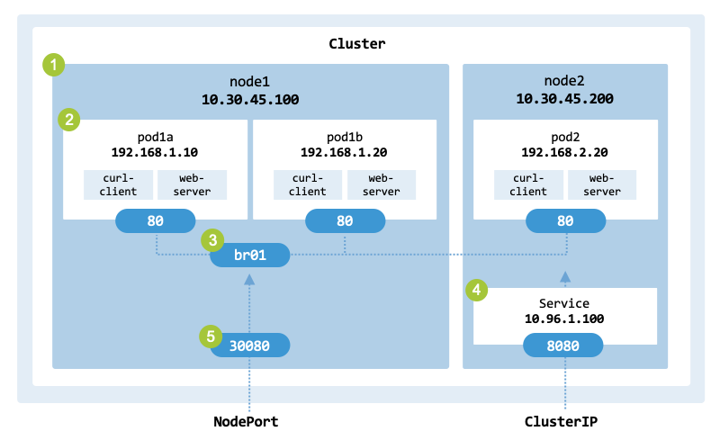
Architecture of the ClusterIP and NodePort services to implement.#
The architecture has the following main components:
A cluster with 2 worker nodes named node1 (10.30.45.100) and node2 (10.30.45.200).
Each worker node runs one or more Pods implemented in the previous chapter.
node1 has two Pods:
pod1a is assigned the IP address 192.168.1.10
pod1b is assigned the IP address 192.168.1.20
node2 has one Pod:
pod2 is assigned the IP address 192.168.2.20
The Pods from node1 are connected to the network through bridge br0.
node2 runs a service with the virtual IP address 10.96.1.100 and port 8080.
node1 has port 30080.
Specification#
lst_nodeport shows the YAML specification
(nodeport.yaml) of the NodePort used as a
running example. The specification defines a NodePort Service that targets a
Deployment of three Pod replicas, which are distributed across nodes node1
and node2. Consistent with the previous chapter, each Pod runs a curl-client
container alongside a web-server (a Python-based HTTP server listening on port 80).
apiVersion: v1
kind: Service
metadata:
  name: http-server-svc
spec:
  type: NodePort
  ports:
  - protocol: TCP
    port: 8080
    targetPort: 80
    nodePort: 30080
  selector:
    app: cs-pod
While the server listens on port 80, clients will interact with the service
via the ClusterIP port 8080 or the NodePort 30080.
We also provide a ClusterIP configuration (clusterip.yaml),
which follows the same logic as the NodePort Service, as a NodePort
inherently includes a ClusterIP for internal routing.
Objectives#
The running example demonstrates several important Kubernetes concepts:
ClusterIP: Virtual IP, local load balancing, and routing of internal traffic.
NodePort: Port mapping on the node’s physical interfaces and IP masquerading for external traffic.
LoadBalancer: External load balancing.
ExternalName: Maps an internal Service name to an external DNS record (CNAME).
You can start the deployment using the following command:
$ kubectl apply -f nodeport.yaml
deployment.apps/nodeport created
In Kubernetes, a Service is just a routing rule; it requires a Deployment to actually run the containers. Once the Pods are created, the kubectl get pods -o wide command provides detailed information about the system deployed:
$ kubectl get pods -o wide

NAME                       READY   ...     IP              NODE
cs-prod-6c65f4f99d-86d6h   2/2     ...     10.244.92.131   node1
cs-prod-6c65f4f99d-rbnxr   2/2     ...     10.244.93.132   node2
To test the web server on node1 (the Service port 8080 is only reachable via the virtual ClusterIP from inside the cluster, while the NodePort 30080 allows external access):
$  curl node1:30080

HTTP Server IP address: 10.244.92.131
Request path: /
We will explain how to perform a manual deployment and configure the network to achieve the same results as above.
Linux primitives#
When a client makes a call to a Kubernetes service, the packets are processed
by several components at the receiving node as illustrated in linux_packet_flow.
The figure shows the incoming packet path from the network to the application.
The path is called the Linux packet flow.
The main components involved are the NIC, with its network interfaces,
the iptables / Netfilter, Conntrack, the bridges, the virtual interfaces
connecting the Pods, the namespaces, the sockets receiving the packets, and the
process receiving the information.
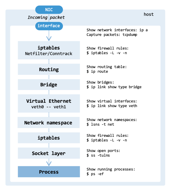
Linux packet flow.#
The overall path that a network packet takes inside a Linux-based network stack to reach a Pod can be described as follows:
NIC: The packet arrives at the physical Network Interface Card of a node.
Interface: The driver handles the hardware interrupt and “hands off” the packet from the ring buffer to the kernel network stack, identifying it as having arrived on, for example, eth0.
iptables: If the packet is destined for a Kubernetes service, it is translated to a specific Pod IP address before a final routing decision is made. Netfilter is responsible for packet filtering and NAT, while conntrack keeps track of existing connections.
Routing table: The kernel examines the destination IP. Since the IP has been translated to a Pod IP, the kernel routes the packet to a local interface (or a remote node).
Bridge: The packet enters the virtual network bridge connecting multiple network interfaces.
Virtual Ethernet: The packet enters the “host side” of the virtual Ethernet pair (for example, veth-host-x).
Network namespace: The packet crosses the link and appears inside the Pod’s private network namespace as, for example, ens3 or eth0.
iptables: The packet passes through the iptables chains.
Socket layer: The kernel searches for a matching socket using the 5-tuple (source IP, source port, destination IP, destination port, and protocol).
Process: The request reaches the receiving process. The data is copied from kernel space to user space for the application (for example, NGINX).
The following sections describe how Netfilter, Conntrack, iptables, and routing work in the network stack.
Netfilter#
Netfilter is a framework of hooks embedded within the Linux kernel’s networking stack. As packets traverse the stack, these hooks are invoked, enabling kernel modules to register callbacks that can inspect, modify, or make routing decisions about each packet. Kubernetes uses Netfilter for packet filtering, network address and port translation (NAT). It is used to route traffic to Pods and to configure security policies at the network level.
Netfilter has five main hooks:
PREROUTING: Activated as soon as a packet arrives from an external source, before any routing decision is made.
INPUT: Applies when a packet is addressed to a local IP on the machine.
FORWARD: Handles packets that are being routed through the system, where neither the source nor destination IP belongs to the local machine.
OUTPUT: Applies to packets generated locally that are about to leave the machine.
POSTROUTING: Takes effect just before any packet exits the machine, regardless of its origin.
fig_netfilter_flow illustrates how the hooks are organized within
the network interface and processes:
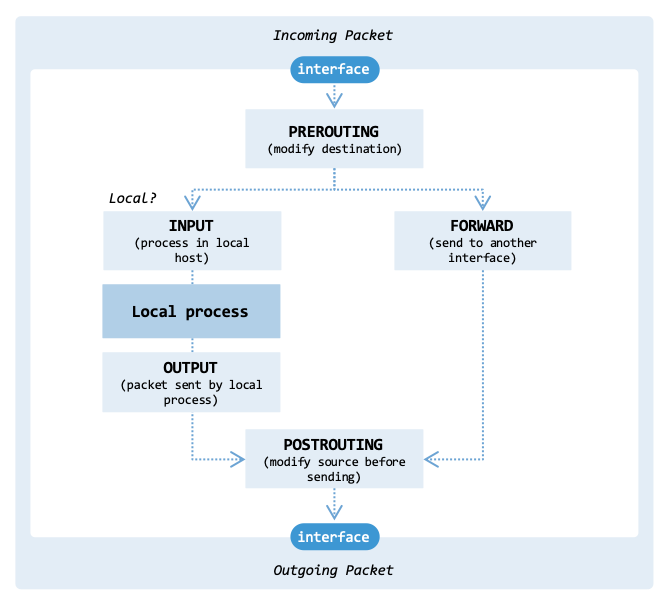
Organization of the various hooks from Netfilter.#
There are three important scenarios to consider when implementing Kubernetes services:
Incoming packet: When an external packet arrives, the PREROUTING hook handles the packet first. Subsequently, the kernel performs a routing lookup; if it determines the destination is local, the packet is passed to the INPUT hook.
Outgoing packet: When a local process sends a packet, the kernel selects the interface to use (e.g., eth0). The OUTPUT hook determines whether the packet is allowed to proceed. Afterwards, the POSTROUTING hook can modify the IP addresses of the packet.
Forwarding packet: When an external packet arrives, it is handled by the PREROUTING hook. The kernel realizes the destination IP is not local and looks up the route to find the exit interface. The packet goes through the FORWARD hook. Afterwards, the POSTROUTING hook can modify the IP addresses of the packet.
Kubernetes uses Netfilter primarily to implement services and network policies. This is managed by the kube-proxy component running on every node. When implementing a ClusterIP service, kube-proxy configures Netfilter to intercept packets at the PREROUTING or OUTPUT hook. It leverages Netfilter’s NAT capabilities to rewrite the destination IP from the Service VIP to the IP of a backend Pod (using probabilistic load balancing). When a Pod communicates with an external network, its source IP must be changed to the node’s IP so the response can find its way back. In this scenario, kube-proxy configures Netfilter to use masquerading in the POSTROUTING hook.
tbl_mapping_of_netfilter_hooks maps the Netfilter hooks to Linux kernel
networking functions.
The code of the various hooks is available under directory
/net/ipv4/ of the
IPv4 networking stack of the kernel source code.
Hook |
Variable |
Function |
File |
|---|---|---|---|
PREROUTING |
|
ip_rcv() |
ip_input.c |
INPUT |
|
ip_local_deliver() |
ip_input.c |
FORWARD |
|
ip_forward() |
ip_forward.c |
OUTPUT |
|
ip_build_and_send_pkt() |
ip_output.c |
POSTROUTING |
|
ip_output() |
ip_output.c |
The following code shows the ip_rcv() function, which handles incoming packets. When a network interface receives an IP packet, the function performs validation, fragmentation handling, and routing.
The function ip_route_input() is called to determine the packet’s destination: whether the packet is destined for the local host, should be routed to another interface, or is a broadcast/multicast packet. The function NF_HOOK() triggers the NF_INET_PRE_ROUTING hook.
// SPDX-License-Identifier: GPL-2.0
/*
 *  net/ipv4/ip_input.c
 *
 *  Handling of incoming IP packets.
 */

#include <linux/kernel.h>
#include <linux/module.h>
...

/* Entry point for incoming packets */
int ip_rcv(struct sk_buff *skb, struct net_device *dev,
           struct packet_type *pt, struct net_device *orig_dev)
{
    const struct iphdr *iph;
    struct rtable *rt;

    skb = skb_share_check(skb, GFP_ATOMIC);
    if (skb == NULL)
        goto out;

    if (!pskb_may_pull(skb, sizeof(struct iphdr)))
        goto drop;

    iph = ip_hdr(skb);

    if (iph->ihl < 5 || iph->version != 4)
        goto drop;

    if (!pskb_may_pull(skb, iph->ihl * 4))
        goto drop;

    if (ip_fast_csum((u8 *)iph, iph->ihl))
        goto drop;

    skb->protocol = htons(ETH_P_IP);
    skb_reset_network_header(skb);

    if (ip_is_fragment(iph)) {
        if (ip_defrag(skb, IP_DEFRAG_LOCAL_DELIVER))
            goto drop;
    }

    rt = ip_route_input(skb, iph->daddr, iph->saddr, iph->tos, dev);
    if (IS_ERR(rt))
        goto drop;

    skb_dst_set(skb, &rt->dst);

    nf_reset(skb);
    return NF_HOOK(NFPROTO_IPV4, NF_INET_PRE_ROUTING, skb, dev,
                   skb->dev, ip_rcv_finish);

drop:
    kfree_skb(skb);
out:
    return NET_RX_DROP;
}
Modifying the Netfilter implementation is generally only necessary in advanced scenarios, such as defining specialized firewall rules for custom load balancers or integrating with customized monitoring systems.
Although this section focuses on the traditional Netfilter/iptables model, it is increasingly being replaced by Netfilter/nftables. Nftables has a simpler syntax and better performance. Another alternative is eBPF (Extended Berkeley Packet Filter), which enables custom programs to run at many points within the kernel. eBPF is covered in Chapter Network Observability.
In high-performance environments, Netfilter may be bypassed altogether. Frameworks such as DPDK (Data Plane Development Kit) move packet processing out of the kernel and into user space. This approach bypasses the kernel networking stack to achieve maximum throughput.
Conntrack#
Conntrack is a component of Netfilter, used to track the state of network connections. It associates TCP, UDP, ICMP, etc. packets with a particular connection. A connection is identified by a tuple (or flow):
(
L3 protocol,source address,source port,destination address,destination port,L4 protocol)
It also tracks the state of connections: NEW, ESTABLISHED, INVALID, or UNTRACKED. The state NEW indicates that the first packet (e.g., the first SYN packet in a TCP handshake) of a connection was seen. The state ESTABLISHED indicates that packets were seen in both directions. The connection table stores information about each ongoing connection and automatically removes entries that have expired due to inactivity.
Besides supporting packet filtering, conntrack provides features to support Network Address Translation (NAT). When performing NAT, conntrack records the translation to reroute incoming packets to the original internal address (and/or port). There are various types of NAT tasks, such as SNAT, DNAT, dynamic NAT, and static NAT. Source NAT (SNAT) translates a private address to a public address to enable access to the internet. With destination NAT (DNAT), the destination address of incoming traffic is translated to an internal address. Dynamic NAT selects and assigns an address from a pool of available addresses. The translation is temporary. In the case of static NAT, the translation is permanent.
The command-line tool conntrack is used to view, add, delete, and modify the tracking table. For example, the option -L enables viewing all the current connections.
$ sudo conntrack -L

udp 17 16 src=192.168.5.127 dst=172.217.23.99 sport=36679 dport=443
 src=172.217.23.99 dst=192.168.5.127 sport=443 dport=36679 mark=0 use=1
udp 17 19 src=192.168.122.1 dst=192.168.122.255 sport=17500 dport=17500
 [UNREPLIED] src=192.168.122.255 dst=192.168.122.1 sport=17500
 dport=17500 mark=0 use=1
tcp 6 431986 ESTABLISHED src=192.168.5.11 dst=216.58.206.32 sport=50226
 dport=443 src=216.58.206.46 dst=192.168.5.127 sport=443 dport=50226
 [ASSURED] mark=0 use=1
...
Since conntrack is integrated with iptables, rules can match packets based on their connection state. The following example creates an INPUT rule that is only applied when the state is ESTABLISHED.
$ sudo iptables -A INPUT -m conntrack --ctstate ESTABLISHED -j ACCEPT
In Kubernetes, kube-proxy sets up DNAT rules that redirect traffic from a Virtual IP to a specific backend Pod’s IP. Once the first packet of a connection is redirected, conntrack internally records this mapping. Afterwards, conntrack ensures packets in that flow are redirected in the same way, and that return traffic from the Pod undergoes reverse translation (de-NAT) back to the service VIP. Without conntrack’s state tracking, the return packets would arrive at the client with the Pod’s IP as the source. Since the client initiated the connection to the Virtual IP, it would not recognize the Pod’s IP and would drop the packet (typically via a TCP RST).
iptables#
While Netfilter is a set of hooks inside the Linux kernel’s network stack and
conntrack records the state of active connections,
iptables is a user-space command-line tool used to configure Netfilter.
tbl_mapping_netfilter_hooks_to_iptables maps the Netfilter hooks to
the iptables chains and use cases.
Hook |
Use case |
Example |
|---|---|---|
PREROUTING |
Port forwarding and redirecting external traffic to an internal IP. |
|
INPUT |
Allow or block traffic reaching the system. For example, allowing SSH access. |
|
FORWARD |
Forward traffic between network interfaces. For example, to forward traffic to an internal IP. |
|
OUTPUT |
Allow, block, or NAT outgoing traffic. |
|
POSTROUTING |
SNAT / MASQUERADE. For example, to change the source IP of packets to enable Internet access. |
|
The configuration rules are generally based on the following criteria:
IP source or destination address
Protocol type: e.g., TCP, UDP, ICMP, OSPF
TCP or UDP source and destination ports
TCP flag bits, such as SYN, ACK, and others
Whether packets are entering or leaving the network interface
For instance, if an organization wants to deny incoming SSH connections except to one jump server (192.168.1.5), it can block incoming TCP SYN segments except those with a destination port of 22 and the destination IP address of the jump server.
sudo iptables -A INPUT -m conntrack \
    --ctstate ESTABLISHED,RELATED -j ACCEPT

sudo iptables -A INPUT -p tcp --dport 22 -d 192.168.1.5 --syn -j ACCEPT
sudo iptables -A INPUT -p tcp --dport 22 --syn -j DROP
Traditional packet filters make decisions on each network packet independently. In contrast, stateful filters track TCP connection states to make context-aware filtering decisions. For example, the following rule allows incoming TCP connections to port 80 only for new connections or already-established connections:
sudo iptables -A INPUT -p tcp --dport 80 -m conntrack \
    --ctstate NEW,ESTABLISHED -j ACCEPT
While iptables is a popular tool for managing network traffic, it has several
limitations for complex environments such as Kubernetes.
iptables uses a linear rule table lookup, which means the time to process packets
increases linearly with the number of rules (fig_iptables_ipvs).
Additionally, the latency to update rules is considerable because iptables
requires the entire ruleset to be replaced atomically rather than supporting
individual rule updates.
Thus, when the scale of a Kubernetes cluster is large, other tools, such as
IPVS (IP Virtual Server), are preferred.
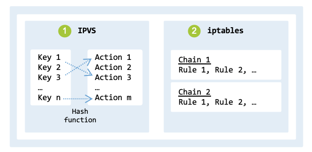
iptables versus IPVS.#
While iptables was developed to support packet filtering and NAT, IPVS was developed for load balancing. Thus, IPVS has additional features such as round-robin, least connection, and destination hashing load balancing.
The command line below adds (option -A) a new virtual server, listening on the IP address 192.168.0.5 and port 80. The option -t indicates that the virtual server will handle TCP traffic. Option -s rr (short for –scheduler rr) indicates that the scheduling algorithm to use is round robin.
$ sudo ipvsadm -A -t 192.168.0.5:80 -s rr
$ sudo ipvsadm -a -t 192.168.0.5:80 -r 192.168.0.101:8080 -m
$ sudo ipvsadm -a -t 192.168.0.5:80 -r 192.168.0.102:8080 -m
Commands 2 and 3 add two backend servers that will handle the actual HTTP requests.
Routing#
Kubernetes relies on routing to enable a flat networking model, where every Pod can communicate with any other Pod without address translation. Each node in a cluster acts as a router for the Pod subnets assigned to it. When a Pod sends a packet to a destination outside its own node, the network manager ensures that the Linux routing table has the necessary routes. This routing might happen via simple static routes or an overlay network (as described in Cluster Networking).
In Linux, routing is the action of guiding network packets from one network interface to another. The routing table is a data structure that stores routes, which are the paths data packets take to reach their destination interface. The routing table maps destination networks to a gateway IP address and outgoing interface. It is used by the kernel to decide where to send packets. As already discussed, each network namespace has its own independent routing table. This allows network configurations to be isolated between different namespaces.
The following commands demonstrate how to display the active routes:
$ route -n

Kernel IP routing table
Destination    Gateway        Genmask        Flags  ...  Iface
default        192.168.178.1  0.0.0.0        UG          wlp0s20f3
172.17.0.0     0.0.0.0        255.255.0.0    U           docker0
192.168.0.0    0.0.0.0        255.255.255.0  U           br-a2bf
192.168.122.0  0.0.0.0        255.255.255.0  U           virbr0
192.168.178.0  0.0.0.0        255.255.255.0  U           wlp0s20f3
The most relevant columns of the table are Destination, Gateway, Genmask, and Iface. The destination indicates the IP address or network. If the Gateway is 0.0.0.0, the destination is directly reachable on the local link; otherwise, it specifies the next-hop IP address. The gateway is the next-hop IP address to which packets should be forwarded. The genmask is the network mask to be applied to the destination network. The Iface, or interface, is the network interface (e.g., eth0, wlan0) to which the packets should be sent. When a route specifying a subnet and a next-hop gateway is added, packets destined for any IP address within the subnet will be sent to the gateway. The gateway then forwards the packets to their final destination.
Let us assume the following route:
ip route add 192.168.2.0/24 via 192.168.1.1
In this example:
192.168.2.0/24 specifies the destination subnet.
192.168.1.1 is the gateway through which packets should be routed.
Let us assume that node node1 (192.168.1.2) sends packets to node node2 (192.168.2.3). Packets are routed as follows:
Table Lookup: The Kernel checks if the destination IP address falls within the 192.168.2.0/24 subnet.
Next Hop: The routing table indicates that packets for the 192.168.2.0/24 subnet should be sent to the gateway 192.168.1.1.
ARP Lookup: The Kernel performs an ARP lookup to find the MAC address of the gateway 192.168.1.1 (if not in the cache, it broadcasts an ARP request on the local network).
Packet Forwarding: The packet is encapsulated in a frame with the gateway’s MAC address and sent out through the network interface specified in the routing table entry.
Gateway Processing: The gateway receives the packet and inspects its destination IP. It forwards it to the next hop or directly to the final destination.
In the previous example, the route was manually configured. Complex networks generally use dynamic routing protocols such as OSPF (Open Shortest Path First), BGP (Border Gateway Protocol), or RIP (Routing Information Protocol) which dynamically adapt to changes in network topologies.
Services types#
Kubernetes supports four types of services, each addressing specific
networking requirements: ClusterIP, NodePort, LoadBalancer, and
ExternalName, as shown in fig_service_types:
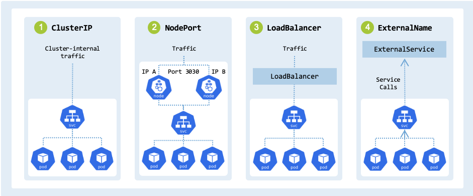
Service types in Kubernetes.#
tbl_service_types describes each type, outlining its function.
Service type |
Description |
Access |
|---|---|---|
ClusterIP |
Service accessible within the cluster |
Cluster-internal IP |
NodePort |
Service reachable from outside the cluster |
|
LoadBalancer |
Provision of an external load balancer that routes traffic to the Service |
Public Cloud IP |
ExternalName |
Maps a service name to an external DNS name |
External DNS |
In Kubernetes, kube-proxy is a component that manages the routing of traffic to the target Pods within the cluster. For example, when a service is created, kube-proxy (operating in iptables mode) automatically sets up iptables rules to forward traffic to one of the available Pods behind the service. Each service type can be implemented using Linux technologies, namely:
ClusterIP: We provide a virtual IP (VIP) in front of the Pods pod1a, pod1b, and pod2 that provide the service. To route and load balance requests, we use iptables and NAT (Network Address Translation).
NodePort: We make the service reachable from outside the cluster by allocating a static port on each node IP address. We use iptables for port forwarding and traffic routing.
LoadBalancer: Provides load balancing across worker nodes. A native Linux implementation can use HAProxy, NGINX, or Envoy to distribute the traffic. We will not provide an implementation since this service type generally relies on an external cloud provider.
ExternalName: We map a service name to an external DNS name. Our implementation uses the DNS server CoreDNS to which CNAME records are added.
ClusterIP#
A service of type ClusterIP exposes a set of Pods to other objects inside
the cluster.
More specifically, it exposes a permanent, stable Virtual IP (VIP) address for
a set of Pods at Layer 4 (TCP/UDP).
The IP is accessible by other Pods and nodes within the same cluster.
For example, a Pod within a cluster can access a ClusterIP service at
<service-name>:<port>.
The VIP is used to forward and load-balance traffic to the backend Pods, since
their IP addresses can change dynamically.
The service and its VIP remain stable even as the underlying backend Pods are
created, destroyed, or replaced.
A ClusterIP service is typically used for databases, backend services, and
other systems that do not need to be exposed externally.
lst_http_server_clusterip defines a service named http-server-svc:
apiVersion: v1
kind: Service
metadata:
  name: http-server-svc
spec:
  type: ClusterIP
  clusterIP: 10.96.1.100
  ports:
    - protocol: TCP
      port: 8080
      targetPort: 80
  selector:
    app: cs-pod
It has the following characteristics:
It is assigned the static cluster-internal IP
10.96.1.100. When not specified, Kubernetes automatically assigns a free IP from its pool toclusterIP.It listens on
port: 8080.When a request hits
clusterIP: 10.96.1.100onport: 8080, the service load-balances traffic to porttargetPort: 80on one of the matching backend Pods.Backend Pods match the selector
app=cs-poddefined in the Service spec.
We implement the ClusterIP specification using the following traffic flow:
Call: The user sends a request to the virtual service address ($VIP:$VIP_PORT).
Interception: iptables rules on the host node intercept the packet.
Transformation: The rules perform destination NAT, replacing the virtual IP and port with the IP and targetPort of a backend Pod.
Routing:
If the backend Pod resides on node2, the Linux Bridge (or veth pair) switches/routes the packet to the target Pod’s network namespace.
Otherwise, the kernel routes the packet from the source node (node2) to the target node (node1).
Upon reaching node1, the network routes the packet to the specific container interface.
Delivery: The request reaches the backend Pod at pod1a, pod1b, or pod2.
Step 1: Create the cluster
Execute the steps to configure the cluster, nodes, Pods, and bridge as described in Section Create cluster.
Step 2: The Virtual IP
Conceptually, a ClusterIP is a virtual IP that clients use to access the
backend Pods. The ClusterIP is assigned dynamically from a predefined IP
range (e.g., 10.96.0.0/16).
Verify that the $VIP and $VIP_PORT are set on each node as specified
in the cluster_vars.env file.
The output should be similar to the following:
$ echo "ClusterIP: $VIP:$VIP_PORT"
ClusterIP: 10.96.1.100:8080
On node1 and node2, ensure the chosen VIP is not already assigned to a network interface or reachable on the network (if it is, choose another IP). A ‘Destination Net Unreachable’ or ‘100% packet loss’ response confirms that the IP is available for use as a virtual address.
$ ping $VIP -c 2

PING 10.96.1.100 (10.96.1.100) 56(84) bytes of data.
From 212.18.6.44 icmp_seq=1 Destination Net Unreachable
From 212.18.6.44 icmp_seq=2 Destination Net Unreachable

--- 10.96.1.100 ping statistics ---
2 packets transmitted, 0 received, +2 errors, 100% packet loss, time 1002ms
Step 3: The “Service” logic (iptables)
On node1, we can access the Pod’s HTTP server directly using their IP
address and port; for example, by using $POD1A_IP:
$ curl $POD1A_IP:$POD_PORT

HTTP Server IP address: 192.168.1.10
Request path: /
Nevertheless, the $VIP cannot be used to access a Pod since no routing
rules to the backend Pods have been created.
It does not exist on any physical network interface.
If you try to curl or ping it, the traffic goes nowhere:
$ curl -v --connect-timeout 2 $VIP:$VIP_PORT

*   Trying 10.96.1.100:8080...
* ipv4 connect timeout after 2000ms, move on!
* Failed to connect to 10.96.1.100 port 8080 after 2003 ms: Timeout was reached
* Closing connection
curl: (28) Failed to connect to 10.96.1.100 port 8080 after 2003 ms: Timeout was reached
When a new Service is created, kube-proxy installs a VIP and a series of iptables rules that redirect traffic from the virtual IP address to backend Pods. kube-proxy creates a chain per service and configures KUBERNETES-SERVICES jump to the respective service chain based on the destination. The logical flow of packets through the various iptables chains includes:
PREROUTING to rewrite the destination VIP for traffic arriving from other nodes or external sources.
OUTPUT to rewrite the destination VIP for traffic originating from a process on the local node.
POSTROUTING to perform SNAT/Masquerading, ensuring the backend Pod sees an IP address that it can route back to if necessary.
A DNAT rule is required to redirect traffic from the VIP to the backend Pods.
The rule is added to the OUTPUT chain of the NAT table for locally generated
traffic. In the Linux kernel, a packet from a local process undergoes an initial
routing lookup to determine its path, but iptables DNAT rules in the OUTPUT
chain can then intercept and rewrite the destination. If the destination is
changed, the kernel performs a reroute check to ensure the packet is sent through
the correct interface for the new destination IP.
This rule applies to traffic originating from a process running on that specific node.
The script clusterip.sh simulates the behavior of kube-proxy for educational purposes.
The function setup_vip1() rewrites packets that match the destination
$VIP:$VIP_PORT to the actual Pod IP $POD1A_IP:$POD_PORT:
setup_vip1() {

    echo "Setting up VIP."

    echo "Adding rule: $VIP:$VIP_PORT -> $POD1A_IP:$POD_PORT"
    sudo iptables -t nat -A OUTPUT -p tcp -d $VIP --dport $VIP_PORT \
         -j DNAT --to-destination $POD1A_IP:$POD_PORT \
         -m comment --comment "PSEUDO_POD_OUTPUT_DNAT_N1"

    echo "Completed."
}
On node1, execute the setup_vip1() function from the script clusterip.sh:
$ clusterip.sh vip node1

Setting up VIP.
Adding rule: 10.96.1.100:8080 -> 192.168.1.10:80
Completed.
After executing the script, you should be able to curl the VIP and receive a response from the backend Pod using the following command:
$ curl $VIP:$VIP_PORT

HTTP Server IP address: 192.168.1.10
Request path: /
The command curl $VIP:$VIP_PORT works without a specific host route for the
VIP because iptables intercepts the packet in the NAT table’s OUTPUT chain and
performs DNAT before the packet leaves the network stack.
This is because packets are intercepted by the iptables DNAT rules before thec
operating system consults the routing table.
The response packet uses the conntrack table (see Section Conntrack) to
reverse the initial DNAT translation, ensuring the response is delivered to the
curl client with the source IP appearing as the original $VIP.
Step 4: Setup Node-to-Pod communication
On node2, it is not possible to access the Pods on node1.
$ curl --connect-timeout 2 $POD1A_IP:$POD_PORT

curl: (28) Failed to connect to 192.168.1.10 port 80 after 2003 ms: Timeout was reached
We are able to curl the $POD1A_IP from node1, but not from node2
since the host routing table has no entry for the remote Pod CIDR.
In production deployments, tools such as Keepalived, HAProxy, and BGP (Border
Gateway Protocol) are used to manage and advertise routes to the $VIP and
$POD1A_IP.
We will use a simpler approach by adding a static route on node2 to route
traffic sent to $POD1A_IP to node1.
On node2, we use the ip route command to add an entry to the kernel’s
routing table that directs traffic for the $POD1A_IP to node1’s IP address.
setup_static_routing2() {

    echo "Setting up static routing (NODE2_IP)"

    echo "Adding static route for $POD1A_IP via $NODE1_IP"
    sudo ip route add $POD1A_IP via $NODE1_IP
    echo "Adding static route for $POD1B_IP via $NODE1_IP"
    sudo ip route add $POD1B_IP via $NODE1_IP

    echo "Completed."
}
On node2, execute the setup_static_routing2() function from the script
clusterip.sh:
$ clusterip.sh static_routing node2

Setting up static routing (NODE2_IP)
Adding static route for 192.168.1.10 via 10.30.45.100
Adding static route for 192.168.1.20 via 10.30.45.100
Completed.
A route to pod1a (192.168.1.10) via node1 (10.30.45.100) has been
added to the routing table:
$ ip route get $POD1A_IP

192.168.1.10 via 10.30.45.100 dev ens3 src 10.30.45.200 uid 1000
    cache
Let’s try to curl $POD1A_IP from node2:
$ curl $POD1A_IP:$POD_PORT

HTTP Server IP address: 192.168.1.10
Request path: /
Similarly, on node1, it is not possible to access the Pods on node2.
To fix this, we add a static route on node1 to route traffic destined to pod2.
setup_static_routing1() {

    echo "Setting up static routing (NODE1_IP)."

    echo "Adding static route for $POD2_IP via $NODE2_IP"
    sudo ip route add $POD2_IP via $NODE2_IP

    echo "Completed."
}
On node1, execute the setup_static_routing1() function from the script
clusterip.sh:
$ clusterip.sh static_routing node1

Setting up static routing (NODE1_IP).
Adding static route for 192.168.2.20 via 10.30.45.200
Completed.
Thus, when you try to curl the $POD2_IP from node1, it works as expected:
$ curl $POD2_IP:$POD_PORT

HTTP Server IP address: 192.168.2.20
Request path: /
Step 5: Setup Pod-to-Pod communication
On node2, let’s try to curl the $POD1A_IP from inside the pod2.
$ sudo ip netns exec $POD2_NAME curl $POD1A_IP:$POD_PORT

HTTP Server IP address: 192.168.1.10
Request path: /
The command succeeds because the script pod_manager.sh added a default route
to its respective node using the command ip route add default via $HOST_IP:
sudo ip netns exec "$POD_NS" ip link set "$POD_VETH" up
sudo ip netns exec "$POD_NS" ip link set lo up
Without the default route, the following error would have been displayed:
$ sudo ip netns exec $POD2_NAME curl $POD1A_IP:$POD_PORT
curl: (7) Failed to connect to 192.168.1.10 port 80 after 0 ms: Could not connect to server
This error indicates that the operating system has no route to the destination network, preventing the packet from leaving the source namespace.
While the above configuration works, it is typically not possible to access the internet from within pod2. On node2, the following command results in an error:
$ sudo ip netns exec $POD2_NAME ping -c 3 -W 0.2 8.8.8.8
PING 8.8.8.8 (8.8.8.8) 56(84) bytes of data.

--- 8.8.8.8 ping statistics ---
3 packets transmitted, 0 received, 100% packet loss, time 2041ms
When traffic leaves a private network (such as 192.168.2.0/24) destined for the public internet (8.8.8.8), the source IP needs to be translated (MASQUERADED) to a globally routable IP address (node2’s IP). If node2 is missing the appropriate iptables rule in the NAT table’s POSTROUTING chain, the packet leaves node2 with the private source IP of pod2. The external router will not know how to route replies to a private IP address and will drop the packet.
To enable Internet access from within pod2, execute the following function in the clusterip.sh script:
setup_postrouting() {

    echo "Setting up postrouting (NODE2_IP)."

    NODE=$(ip a show $NODE_IFACE | grep 'inet ' | awk '{print $2}' | cut -d/ -f1)
    echo "Adding SNAT MASQUERADE rule: POD2_IP ($POD2_IP) -> NODE2_IP ($NODE:$NODE_IFACE)"
    sudo iptables -t nat -A POSTROUTING \
         -s $POD2_IP ! -d $POD1_SUBNET --out-interface $NODE_IFACE \
         -j MASQUERADE -m comment --comment "PSEUDO_POD_MASQ"

    echo "Completed."
}
The rule is applied only to traffic not destined for the Pod subnet of node1
($POD1_SUBNET), ensuring that internal cross-node Pod traffic retains its
original source IP for logging and security policy purposes, while external
traffic is translated.
On node2, execute the setup_postrouting() function from the script clusterip.sh:
$ clusterip.sh postrouting node2

Setting up postrouting (NODE2_IP).
Adding SNAT MASQUERADE rule: POD2_IP (192.168.2.20) -> NODE2_IP (10.30.45.200:ens3)
Completed.
Verify that the iptables rule has been added correctly by displaying the rules in the POSTROUTING chain of the NAT table:
$ sudo iptables -t nat -vL POSTROUTING

Chain POSTROUTING (policy ACCEPT 1 packets, 112 bytes)
pkts bytes target     prot opt in     out     source               destination
    3   252 MASQUERADE  all  --  any    ens3    192.168.2.20/32 !192.168.1.0/24       /* PSEUDO_POD_MASQ */
With this rule, it is possible to ping the internet from within pod2:
$ sudo ip netns exec $POD2_NAME ping -c 1 8.8.8.8

PING 8.8.8.8 (8.8.8.8) 56(84) bytes of data.
64 bytes from 8.8.8.8: icmp_seq=1 ttl=117 time=12.8 ms

--- 8.8.8.8 ping statistics ---
1 packets transmitted, 1 received, 0% packet loss, time 0ms
rtt min/avg/max/mdev = 12.788/12.788/12.788/0.000 ms
Step 6: Load balancing rules
On node2, with the current configuration, there is no load balancing.
To verify this, curl $VIP:$VIP_PORT:
for i in {1..8}; do
    curl -s $VIP:$VIP_PORT | \
    grep "192.168." | \
    sed "s/^/$i: /g"
    sleep 1
done

1: HTTP Server IP address: 192.168.1.10
2: HTTP Server IP address: 192.168.1.10
3: HTTP Server IP address: 192.168.1.10
... 5 additional entries with the same IP address: 192.168.1.10
To add load balancing rules, we will use DNAT rules to distribute traffic
to backend Pods using probabilistic load balancing.
We only show the load balancing across Pods located on node2. Similar rules
can also be applied to node1 (to add load balancing rules to node1, the
existing $VIP rule in the OUTPUT chain must first be deleted).
The setup_load_balancing() function from the clusterip.sh script
creates the rules required to balance traffic across the backend Pods:
setup_load_balancing() {
    echo "Setting up Load Balancing (NODE2_IP)."

    echo "Rule 1: ~33% -> POD1A_IP ($POD1A_IP)."
    sudo iptables -t nat -A OUTPUT -p tcp -d $VIP --dport $VIP_PORT \
       -m statistic --mode random --probability 0.33 \
       -j DNAT --to-destination $POD1A_IP:$POD_PORT \
       -m comment --comment "PSEUDO_POD_OUTPUT_POD1A_IP"

    echo "Rule 2: ~33% -> POD1B_IP ($POD1B_IP)."
    sudo iptables -t nat -A OUTPUT -p tcp -d $VIP --dport $VIP_PORT \
       -m statistic --mode random --probability 0.5 \
       -j DNAT --to-destination $POD1B_IP:$POD_PORT \
       -m comment --comment "PSEUDO_POD_OUTPUT_POD1B_IP"

    echo "Rule 3: Remaining -> POD2_IP ($POD2_IP)."
    sudo iptables -t nat -A OUTPUT -p tcp -d $VIP --dport $VIP_PORT \
       -j DNAT --to-destination $POD2_IP:$POD_PORT \
       -m comment --comment "PSEUDO_POD_OUTPUT_POD2_IP"

    echo "Completed."
}
On node2, execute the setup_load_balancing() function:
$ clusterip.sh load_balancing node2

Setting up Load Balancing rules on NODE2_IP.
Rule 1: ~33% -> POD1A_IP (192.168.1.10).
Rule 2: ~33% -> POD1B_IP (192.168.1.20).
Rule 3: Remaining -> POD2_IP (192.168.2.20).
Completed.
Verify that these three rules implement probabilistic traffic distribution between the three backend servers:
 $ sudo iptables -t nat -L -n -v | grep $VIP

 9  540 DNAT  6  --  *  *  0.0.0.0/0  10.96.1.100  tcp dpt:8080 statistic mode random probability 0.33000000007 /* PSEUDO_POD_OUTPUT_POD1A_IP */ to:192.168.1.10:80
11  660 DNAT  6  --  *  *  0.0.0.0/0  10.96.1.100  tcp dpt:8080 statistic mode random probability 0.50000000000 /* PSEUDO_POD_OUTPUT_POD1B_IP */ to:192.168.1.20:80
11  660 DNAT  6  --  *  *  0.0.0.0/0  10.96.1.100  tcp dpt:8080 /* PSEUDO_POD_OUTPUT_POD2_IP */ to:192.168.2.20:80
Verify the load balancing by accessing the $VIP on port $VIP_PORT from node2:
$ for i in {1..8}; do curl -s $VIP:$VIP_PORT | grep "192.168." | sed "s/^/$i: /g" ; sleep 1; done

1: HTTP Server IP address: 192.168.2.20
2: HTTP Server IP address: 192.168.2.20
3: HTTP Server IP address: 192.168.1.20
4: HTTP Server IP address: 192.168.1.20
5: HTTP Server IP address: 192.168.1.10
6: HTTP Server IP address: 192.168.1.20
7: HTTP Server IP address: 192.168.1.20
8: HTTP Server IP address: 192.168.1.10
Traffic will be load-balanced across the three backend servers. For example:
Requests 5 and 8 go to 192.168.1.10 (pod1a).
Requests 3, 4, 6, and 7 go to 192.168.1.20 (pod1b).
Requests 1 and 2 go to 192.168.2.20 (pod2).
The following output displays the three rules created for the service:
$ sudo iptables-save | grep "PSEUDO_POD"

-A OUTPUT -d 10.96.1.100/32 -p tcp -m tcp --dport 8080 -m statistic --mode random --probability 0.33000000007 -m comment --comment PSEUDO_POD_OUTPUT_POD1A_IP -j DNAT --to-destination 192.168.1.10:80
-A OUTPUT -d 10.96.1.100/32 -p tcp -m tcp --dport 8080 -m statistic --mode random --probability 0.50000000000 -m comment --comment PSEUDO_POD_OUTPUT_POD1B_IP -j DNAT --to-destination 192.168.1.20:80
-A OUTPUT -d 10.96.1.100/32 -p tcp -m tcp --dport 8080 -m comment --comment PSEUDO_POD_OUTPUT_POD2_IP -j DNAT --to-destination 192.168.2.20:80
-A POSTROUTING -s 192.168.2.20/32 ! -d 192.168.1.0/24 -o ens3 -m comment --comment PSEUDO_POD_MASQ -j MASQUERADE
Step 7: Cleanup
The clusterip.sh script includes all the commands to clean up the configuration.
cleanup_node1() {

    echo "Cleaning up NODE1_IP ($NODE1_IP)"

    echo "Deleting local DNAT rule."
    sudo iptables -t nat -D OUTPUT -p tcp -d $VIP --dport $VIP_PORT \
        -j DNAT --to-destination $POD1A_IP:$POD_PORT \
        -m comment --comment "PSEUDO_POD_OUTPUT_DNAT_N1"

    echo "Deleting static route for $POD2_IP via $NODE2_IP"
    sudo ip route del $POD2_IP via $NODE2_IP

    echo "Completed."
}

cleanup_node2() {

    echo "Cleaning up NODE2_IP"

    echo "Deleting Load Balancing rules."

    echo "Rule 1: ~33% chance to go to POD1A_IP ($POD1A_IP)."
    sudo iptables -t nat -D OUTPUT -p tcp -d $VIP --dport $VIP_PORT \
       -m statistic --mode random --probability 0.33 \
       -j DNAT --to-destination $POD1A_IP:$POD_PORT \
       -m comment --comment "PSEUDO_POD_OUTPUT_POD1A_IP"

    echo "Rule 2: 50% of remaining traffic to POD1B_IP ($POD1B_IP)."
    sudo iptables -t nat -D OUTPUT -p tcp -d $VIP --dport $VIP_PORT \
       -m statistic --mode random --probability 0.5 \
       -j DNAT --to-destination $POD1B_IP:$POD_PORT \
       -m comment --comment "PSEUDO_POD_OUTPUT_POD1B_IP"

    echo "Rule 3: 100% of remaining traffic goes to POD2_IP ($POD2_IP)."
    sudo iptables -t nat -D OUTPUT -p tcp -d $VIP --dport $VIP_PORT \
       -j DNAT --to-destination $POD2_IP:$POD_PORT \
       -m comment --comment "PSEUDO_POD_OUTPUT_POD2_IP"

    echo "Deleting MASQUERADE rule."
    sudo iptables -t nat -D POSTROUTING -s $POD2_IP ! -d $POD1_SUBNET \
        --out-interface $NODE_IFACE -j MASQUERADE -m comment --comment "PSEUDO_POD_MASQ"

    echo "Removing static routes."
    sudo ip route del $POD1A_IP via $NODE1_IP 2>/dev/null
    sudo ip route del $POD1B_IP via $NODE1_IP 2>/dev/null

    echo "Completed."
}
On node1, run the following command to clean up the configuration:
$ clusterip.sh cleanup node1

Cleaning up NODE1_IP (10.30.45.238)
Deleting local DNAT rule.
Deleting static route for 192.168.2.20 via 10.30.45.200
Cleanup complete.
On node2, run the equivalent command:
$ clusterip.sh cleanup node2
NodePort#
Building a NodePort service works very similarly to a ClusterIP service,
but with one key addition: it also exposes a dedicated port on every node’s
IP address.
This allows traffic from outside the cluster to reach the cluster and its Pods.
A NodePort is generally used by applications that require direct access to
specific ports on each node. For example, legacy systems or applications that
require persistent client connections. External traffic can reach a service
through <NodeIP>:<NodePort>.
lst_http_server_nodeport defines a service named http-server-svc:
apiVersion: v1
kind: Service
metadata:
  name: http-server-svc
spec:
  type: NodePort
  ports:
  - protocol: TCP
    port: 8080
    targetPort: 80
    nodePort: 30080
  selector:
    app: cs-pod
The specification has the following characteristics:
The service can be accessed from outside the cluster using any node’s IP address at
nodePort: 30080.It listens internally within the cluster on
port: 8080.When a request hits ports
8080or30080, the service load-balances traffic to porttargetPort: 80of one of the matching backend Pods.Backend Pods have the label
app: cs-podmatching the service’s selector.
The NodePort service operates using the following traffic flow:
Call: An external user sends a request to a node’s IP address on the defined port (e.g., node1 on port 30080). The request arrives at the node’s network interface.
Interception: iptables rules on node1 intercept the packet.
Transformation: The rules perform a DNAT, replacing the NodePort with the backend Pod’s address, e.g., pod2. If the selected Pod resides on a different node, source NAT is typically also applied to ensure return traffic flows back through the ingress node.
Routing:
If the selected backend Pod is on the same node, the packet is routed directly to the local Pod’s interface.
If the selected backend Pod is on a different node, the packet is routed across the network from one node to another.
Delivery: The request reaches the backend Pod pod2.
Note
Step 3 can also be implemented by replacing the destination address with the VIP of the ClusterIP.
This section explains how to expose a Service to external traffic using the NodePort mechanism.
Step 1: Create cluster
Execute the steps to configure the cluster, nodes, Pods, and the bridge as described in Section Create cluster. If you have already completed the steps in Section ClusterIP, you only need to clean up the existing deployment before proceeding.
Step 2: The NodePort
When a Kubernetes service is created with the type NodePort, a NodePort is opened on every node in the cluster. A NodePort is a dedicated, static port number (typically in the range of 30000-32767).
Verify that the $NODE_PORT is set on the host and on each node as
specified in the cluster_vars.env file.
The output should be similar to the following:
$ echo "NodePort: ${NODE_PORT}"
NodePort: 30080
We will forward port 30080 to the backend Pods.
Step 3: Handling external traffic
When we built the ClusterIP, we configured the OUTPUT chain because we were
generating traffic on the nodes.
For a NodePort, the traffic is expected to come from outside the cluster.
The kernel processes these packets in the PREROUTING chain.
tbl_external_traffic_flow shows the traffic flow and identifies what
needs to be configured:
Chain |
Action |
|
|---|---|---|
PREROUTING |
DNAT |
Change destination IP: node1 \(\rightarrow\) pod1a, pod1b, or pod2 |
Routing |
Forward packet \(\rightarrow\) br0 \(\rightarrow\) pod1a |
|
Pod |
Pod sends response with the source pod1a and destination node1 |
|
Routing |
Route packet \(\rightarrow\) br0 \(\rightarrow\) node |
|
POSTROUTING |
SNAT |
Change source IP: pod1a \(\rightarrow\) node1 |
Routing |
Forward packet \(\rightarrow\) external network |
|
External client |
Client receives response with source node1 and destination its own IP address |
The function setup_prerouting_external() from the script nodeport.sh
creates a PREROUTING rule to load balance the traffic to the backend Pods.
The rules have the same probabilities as the ones used when we created the ClusterIP:
Rule 1: ~33% chance to go to pod1a
Rule 2: ~33% chance traffic goes to pod1b
Rule 3: Remaining traffic goes to pod2
setup_prerouting_external() {

    echo "Setting load balancing rules (external traffic)"

    echo "Rule 1: ~33% -> POD1A_IP"
    sudo iptables -t nat -A PREROUTING -p tcp -d $NODE1_IP --dport $NODE_PORT \
        -m statistic --mode random --probability 0.33 \
        -j DNAT --to-destination $POD1A_IP:$POD_PORT \
        -m comment --comment "NODEPORT_PREROUTING_EXTERNAL_POD1A"

    echo "Rule 2: ~33% -> POD1B_IP"
    sudo iptables -t nat -A PREROUTING -p tcp -d $NODE1_IP --dport $NODE_PORT \
        -m statistic --mode random --probability 0.5 \
        -j DNAT --to-destination $POD1B_IP:$POD_PORT \
        -m comment --comment "NODEPORT_PREROUTING_EXTERNAL_POD1B"

    echo "Rule 3: Remaining -> POD2_IP"
    sudo iptables -t nat -A PREROUTING -p tcp -d $NODE1_IP --dport $NODE_PORT \
        -j DNAT --to-destination $POD2_IP:$POD_PORT \
        -m comment --comment "NODEPORT_PREROUTING_EXTERNAL_POD2"

    echo "Completed."
}
On node1, execute the setup_prerouting_external() function:
$ nodeport.sh prerouting_external

Setting load balancing rules (external traffic)
Rule 1: ~33% -> POD1A_IP
Rule 2: ~33% -> POD1B_IP
Rule 3: Remaining -> POD2_IP
Completed.
Verify the rules created:
$ sudo iptables -t nat -L -n -v | grep $NODE_PORT

0  0 DNAT  6  --  *  *  0.0.0.0/0  10.30.45.100  tcp dpt:30080 statistic mode random probability 0.33000000007 /* NODEPORT_PREROUTING_EXTERNAL_POD1A */ to:192.168.1.10:80
0  0 DNAT  6  --  *  *  0.0.0.0/0  10.30.45.100  tcp dpt:30080 statistic mode random probability 0.50000000000 /* NODEPORT_PREROUTING_EXTERNAL_POD1B */ to:192.168.1.20:80
0  0 DNAT  6  --  *  *  0.0.0.0/0  10.30.45.100  tcp dpt:30080 /* NODEPORT_PREROUTING_EXTERNAL_POD2 */ to:192.168.2.20:80
Since pod2 resides on node2, on node1, we also need to add a route from node1 to node2:
setup_static_routing() {

    echo "Setting up static routes."

    echo "Adding static route for $POD2_IP via $NODE2_IP"
    sudo ip route add $POD2_IP via $NODE2_IP

    echo "Completed."
}
On node1, execute the setup_static_routing() function:
$ nodeport.sh static_routing

Setting up static routes.
Adding static route for 192.168.2.20 via 10.30.45.200
Completed.
On the host, which is located on a different network than the nodes node1 and node2 of the cluster, test that you can curl the NodePort service:
for i in {1..8}; do
    curl -s $NODE1_IP:$NODE_PORT --connect-timeout 1 | \
    grep "192.168." | \
    sed "s/^/$i: /g"

    sleep 1
done

1: HTTP Server IP address: 192.168.1.10
3: HTTP Server IP address: 192.168.1.20
5: HTTP Server IP address: 192.168.1.10
6: HTTP Server IP address: 192.168.1.10
7: HTTP Server IP address: 192.168.1.10
8: HTTP Server IP address: 192.168.1.10
The curl command fails for pod2 on node2 (request IDs 2 and 4 are missing). When load balancing selects a Pod on node1, the return path is direct because the namespace is local to the node. In our infrastructure, since we are using multipass, node1 acts as the gateway and the return path is already clear. Conntrack handles the reverse DNAT translation so the host thinks it’s talking to node1.
When load balancing selects pod2, the Python server in the namespace receives the packet and sees the source IP as the host IP (because it was not changed). The server replies and sends the packet to the host IP. Since node2 has a direct route to the host via the Multipass bridge, it sends the packet directly back to the host. The host receives a packet from POD2_IP. However, the host is expecting a reply from NODE1_IP (the address it originally called). The host doesn’t recognize this packet and drops it.
You must force the return traffic to go back through node1 so that node1 can reverse the DNAT. You do this by telling node1 to “pretend” the request came from itself. The Python server on node2 will see the source as node1. It will send the reply to node1, which will then correctly de-NAT the packet and send it back to the host.
Another problem that may occur is the following. When a Pod (for example, pod1a) sends a response packet back, it uses the source IP address of the Pod itself (pod1a’s IP) and the destination IP address of the original external client. The problem is that the client only knows about node1’s IP address. When the response packet arrives at the client, it sees pod1a’s IP as the source. Since the client never sent a request to the IP of pod1a, it drops the packet because it doesn’t match any active connection.
To fix these two issues, we apply rules in the POSTROUTING chain to perform SNAT on the response packets as they leave the host, ensuring the source IP is translated back to the external node1’s IP. This makes the packet look like came from the node.
Conntrack on node1 handles the reverse DNAT translation so the host thinks it’s talking to node1.
The function setup_postrouting_external() from the script nodeport.sh
ensures the Pod replies to the host, allowing the host to properly reverse NAT
the packet back to the client.
setup_postrouting_external() {

    echo "Setting postrouting rules (external traffic)."

    BRIDGE_CIDR=$(ip a show br0 | grep 'inet ' | awk '{print $2}')

    echo "Rule 4. Masquerade for local node"
    sudo iptables -t nat -A POSTROUTING -s $BRIDGE_CIDR ! -d $BRIDGE_CIDR \
        -j MASQUERADE -m comment --comment "NODEPORT_POSTROUTING_MASQ_EXTERNAL_LOCAL"

    echo "Rule 5. Masquerade for remote nodes"
    sudo iptables -t nat -A POSTROUTING -p tcp -d $POD2_IP --dport $POD_PORT \
        -j MASQUERADE -m comment --comment "NODEPORT_POSTROUTING_MASQ_EXTERNAL_REMOTE"

    echo "Completed."
}
On node1, execute the setup_postrouting_external() function:
$ nodeport.sh postrouting_external

Setting postrouting rules (external traffic).
Rule 4. Masquerade for local node
Rule 5. Masquerade for remote nodes
Completed.
Verify the rules created:
$ sudo iptables -t nat -L -n -v | grep MASQUERADE

0 0 MASQUERADE 0 -- * * 192.168.1.0/24  !192.168.1.0/24   /* NODEPORT_POSTROUTING_MASQ_EXTERNAL_LOCAL */
0 0 MASQUERADE 6 -- * * 0.0.0.0/0        192.168.2.20     tcp dpt:80 /* NODEPORT_POSTROUTING_MASQ_EXTERNAL_REMOTE */
On the host, verify the new configuration. As expected, the traffic is load-balanced across the three backend Pods.
$ for i in {1..8}; do curl -s $NODE1_IP:$NODE_PORT --connect-timeout 1 | grep "192.168." | sed "s/^/$i: /g" ; sleep 1; done

1: HTTP Server IP address: 192.168.2.20
2: HTTP Server IP address: 192.168.2.20
3: HTTP Server IP address: 192.168.1.20
4: HTTP Server IP address: 192.168.2.20
5: HTTP Server IP address: 192.168.1.10
6: HTTP Server IP address: 192.168.2.20
7: HTTP Server IP address: 192.168.2.20
8: HTTP Server IP address: 192.168.1.10
Step 4: Handling localhost traffic
The local traffic flow for a packet originating from the host itself and destined for a Pod attached to the bridge (br0) follows a different path through iptables. It uses OUTPUT and POSTROUTING chains, and bypasses PREROUTING and INPUT.
This type of traffic is often called a hairpin scenario in networking, and
the DNAT rule from the external traffic flow table must also be applied here for
the connection to work.
tbl_local_traffic_flow shows how the traffic flow needs to be configured:
Chain |
Action |
|
|---|---|---|
OUTPUT |
DNAT |
Change destination IP: node1 \(\rightarrow\) pod1a, pod1b, or pod2 |
Routing |
Forward packet \(\rightarrow\) br0 \(\rightarrow\) pod1a |
|
Pod |
Pod sends response with the source pod1a and destination node1 |
|
Routing |
Route packet \(\rightarrow\) br0 \(\rightarrow\) node1 |
|
POSTROUTING |
SNAT |
Change source IP: pod1a \(\rightarrow\) node1 |
INPUT |
node1 process receives the response from the loopback interface |
On node1, the command curl 127.0.0.1:$NODE_PORT will fail since the kernel
bypasses the PREROUTING chain for local traffic.
The kernel attempts to deliver the packet locally on port $NODE_PORT, but
nothing is listening there, causing the connection to fail.
$ curl 127.0.0.1:$NODE_PORT

curl: (7) Failed to connect to 127.0.0.1 port 30080 after 0 ms: Could not connect to server
To make the NodePort work for the host itself, we need to use the OUTPUT chain
to match packets with destinated for 127.0.0.1:$NODE_PORT.
Thus, we duplicate the rules from the PREROUTING chain to the OUTPUT chain.
The function setup_output_internal() from the script nodeport.sh applies
the DNAT load-balancing rules to the OUTPUT chain for locally generated traffic.
setup_output_internal() {

    echo "Setting load balancing rules (internal traffic)."

    echo "Rule 6: ~33% -> POD1A_IP"
    sudo iptables -t nat -A OUTPUT -p tcp -d 127.0.0.1 --dport $NODE_PORT \
        -m statistic --mode random --probability 0.33 \
        -j DNAT --to-destination $POD1A_IP:$POD_PORT \
        -m comment --comment "NODEPORT_OUTPUT_INTERNAL_POD1A"

    echo "Rule 7: ~33% -> POD1B_IP"
    sudo iptables -t nat -A OUTPUT -p tcp -d 127.0.0.1 --dport $NODE_PORT \
        -m statistic --mode random --probability 0.5 \
        -j DNAT --to-destination $POD1B_IP:$POD_PORT \
        -m comment --comment "NODEPORT_OUTPUT_INTERNAL_POD1B"

    echo "Rule 8: Remainder -> POD2_IP"
    sudo iptables -t nat -A OUTPUT -p tcp -d 127.0.0.1 --dport $NODE_PORT \
        -j DNAT --to-destination $POD2_IP:$POD_PORT \
        -m comment --comment "NODEPORT_OUTPUT_INTERNAL_POD2"

    echo "Completed."
}
On node1, execute the setup_output_internal() function:
$ nodeport.sh output_internal

Setting load balancing rules (internal traffic).
Rule 6: ~33% -> POD1A_IP
Rule 7: ~33% -> POD1B_IP
Rule 8: Remainder -> POD2_IP
Completed.
Verify the rules created:
$ sudo iptables -t nat -L -n -v
On node1, the command curl 127.0.0.1:$NODE_PORT will still fail, albeit
differently – curl will hang – since the packets are not able to find their
way to the client:
$ curl --max-time 5 127.0.0.1:$NODE_PORT

curl: (28) Connection timed out after 5003 milliseconds
The node kernel sees a packet destined for 127.0.0.1 arriving through the bridge interface (br0). The kernel knows 127.0.0.1 is only reachable via the loopback interface (lo). Since it is an impossible packet, it is dropped.
The solution is to add a SNAT (Masquerade) rule to change the source IP of the traffic that originated from 127.0.0.1 before it leaves the node network stack and enters the Pod namespace.
The function setup_postrouting_internal() from the script nodeport.sh
configures the host to allow routing loopback traffic and adds the MASQUERADE
rules to the POSTROUTING chain.
setup_postrouting_internal() {

    echo "Setting postrouting (internal)."

    echo "Setting route_localnet for bridge $BRIDGE_NAME"
    sudo sysctl -w net.ipv4.conf.$BRIDGE_NAME.route_localnet=1

    BRIDGE_CIDR=$(ip a show br0 | grep 'inet ' | awk '{print $2}')

    echo "Rule 9. Masquerade for local node"
    sudo iptables -t nat -A POSTROUTING -d $BRIDGE_CIDR -j MASQUERADE \
        -m comment --comment "NODEPORT_POSTROUTING_MASQ_INTERNAL_LOCAL"

    echo "Rule 10. Masquerade for remote nodes"
    sudo iptables -t nat -A POSTROUTING -p tcp -s 127.0.0.1 \
        -d $POD2_SUBNET --dport $POD_PORT -j SNAT --to-source $NODE1_IP \
        -m comment --comment "NODEPORT_POSTROUTING_SNAT_INTERNAL"

    echo "Completed."
}
On node1, execute the setup_postrouting_internal() function:
$ nodeport.sh postrouting_internal

Setting postrouting (internal).
Setting route_localnet for bridge br0
net.ipv4.conf.br0.route_localnet = 1
Rule 9. Masquerade for local node
Rule 10. Masquerade for remote nodes
Completed.
On node1, re-executing the command curl 127.0.0.1:$NODE_PORT will now
work:
$ curl 127.0.0.1:$NODE_PORT

HTTP Server IP address: 192.168.1.20
Request path: /
This forces the Pod to reply to the host’s bridge IP, ensuring that the return packet follows a valid route.
On node1, run the following command to clean up the configuration:
$ nodeport.sh cleanup

Teardown of external traffic
Rule 1: ~33% -> POD1A_IP
Rule 2: ~33% -> POD1B_IP
Rule 3: Remaining -> POD2_IP
Rule 4. Masquerade for local node
Rule 5. Masquerade for remote nodes
Teardown of internal traffic
Rule 6: ~33% -> POD1A_IP
Rule 7: ~33% -> POD1B_IP
Rule 8: Remainder -> POD2_IP
Rule 9. Masquerade for local node
Rule 10. Masquerade for remote nodes
Deleting static route for 192.168.2.20 via 10.30.45.200
Complete.
LoadBalancer#
Building a LoadBalancer service is similar to a NodePort. The main functional difference is that when using a NodePort, the user must know the IP address of a node and the allocated node port. Traffic enters the cluster directly via a node. With a LoadBalancer service, the user only needs to know the public IP of the cloud load balancer and its port number. It sits in front of all cluster nodes and automatically load-balances external traffic across cluster nodes.
A LoadBalancer service typically integrates with a cloud infrastructure (e.g., AWS ELB/ALB, Google Cloud Load Balancer, Azure Load Balancer) to manage the actual traffic distribution, health checks, and public IP allocation. The load balancing strategy used (e.g., round-robin, least connections, source IP hashing) is often configured by the external cloud provider’s load balancer component, not by the Kubernetes cluster itself.
The following YAML file defines a LoadBalancer service named lb-http-server
with the following characteristics:
It listens on
port: 80for traffic originating from the load balancer or internal cluster components.It uses
protocol: TCP.When a request hits port 80, the service load balances traffic to
targetPort: 8080on one of the matching backend Pods.The service targets backend Pods that have the label
app: cs-pod.
apiVersion: v1
kind: Service
metadata:
  name: lb-http-server
spec:
  type: LoadBalancer
  ports:
    - protocol: TCP
      port: 80
      targetPort: 8080
  selector:
    app: cs-pod
When a service of type LoadBalancer is created, the cloud controller manager calls the cloud provider’s API to provision a dedicated external load balancer. The load balancer is configured to direct traffic to the NodePort assigned to the service on all cluster nodes.
The traffic flow for an external client call is as follows:
Call: An external user sends a request to the public IP address assigned to the cloud provider’s load balancer.
External routing: The cloud load balancer forwards the request to the NodePort of one of the cluster nodes, for example, node2.
Interception: The iptables (or IPVS) rules on node2 are matched against the incoming packet.
Transformation: The destination address is changed to the address of a backend Pod (e.g., pod1a).
Routing:
If the selected backend Pod is on node2, the packet is routed directly to the local Pod’s interface.
If it is on a different node (e.g., node1), the packet undergoes SNAT so that return traffic flows back through node2, and is then routed across the cluster network to node1.
Delivery: The request reaches the backend Pod (pod1a) on node1.
Since the LoadBalancer type is built on top of the NodePort type, and external cloud infrastructure orchestration varies by provider, ensure your environment has a cloud controller manager enabled before applying this manifest.
ExternalName#
A service of type ExternalName is used to create an internal DNS CNAME (Canonical Name) record that maps to an external DNS name. A typical scenario is to set up a service to represent an external database management system. For example, the internal DNS name db-prod can be associated with the external DNS name db-prod.cz9xy8723.us-east-1.rds.amazonaws.com. Internal clients use the DNS name of the internal service as an alias for the external DNS name. Services of type ExternalName do not proxy traffic (like a ClusterIP or NodePort) and do not include any Pod selectors.
For example, the following YAML description enables the name
my-ip-service.default.svc.cluster.local to be resolved by the DNS service
as the CNAME record api.ipify.org.
apiVersion: v1
kind: Service
metadata:
  name: my-ip-service
spec:
  type: ExternalName
  externalName: api.ipify.org
Kubernetes will generate a DNS record <service-name>.<namespace>.svc.cluster.local
in the cluster’s internal DNS server.
The following sequence describes the process of a client application resolving the IP address of the my-ip-service service using a CNAME record in a DNS lookup:
The Application asks DNS: “What is the IP of my-ip-service?”
The DNS replies: “my-ip-service is actually api.ipify.org (CNAME).”
The Application asks DNS: “Understood, what is the IP of api.ipify.org?”
The DNS replies: “It is 104.26.12.205 (A Record).”
In Linux, the simplest implementation of an ExternalName is to add the mapping to the /etc/hosts file. However, this approach does not perfectly mimic behavior of the Kubernetes service; it has several limitations. The hosts file does not support CNAMEs (i.e., mapping name-to-name). It only supports A records (i.e., mapping name-to-IP) and it only works if the external service has a static IP.
Using dedicated DNS services like CoreDNS or dnsmasq is a better approach to managing names than manually editing /etc/hosts, since these services provide dynamic features. We will use CoreDNS because it is the default DNS resolution engine within Kubernetes clusters. Kubernetes used Kube-DNS (which relied on dnsmasq) as its default cluster DNS service before switching to CoreDNS.
On node1, download and extract the CoreDNS server binary:
$ VERSION="coredns_1.13.1_linux_amd64.tgz"
$ curl -LO https://github.com/coredns/coredns/releases/download/v1.13.1/$VERSION
$ tar -xzf $VERSION
$ chmod +x coredns
Since Ubuntu uses the system-wide network name resolution service systemd-resolved, which by default listens on port 53 via a local stub listener, we need to adjust its configuration to free up port 53 before running CoreDNS.
$ sudo systemctl stop systemd-resolved
Configure systemd-resolved to use the IP address DNS=127.0.0.1 as its primary upstream DNS server. The variable DNSStubListener=no stops the local resolver (the “Stub Listener”) from listens on the IP address 127.0.0.53 for DNS queries. This frees up port 53 on the loopback interface, which is necessary to run CoreDNS on the same node.
CONFIG_FILE='/etc/systemd/resolved.conf'
sudo sed -i 's/^#*DNS=.*/DNS=127.0.0.1/' "$CONFIG_FILE"
sudo sed -i 's/^#*DNSStubListener=.*/DNSStubListener=no/' "$CONFIG_FILE"
Configure CoreDNS using the file ./Corefile with a DNS name rewrite combined
with recursive forwarding to external public DNS servers.
The value :53 specifies the standard default port number CoreDNS listens on.
Enable error logging of all handled DNS queries.
The directive rewrite name my-ip.default.svc.cluster.local api.ipify.org
performs a name substitution before the query is processed or forwarded.
All queries (.) are sent to the Cloudflare DNS (1.1.1.1) and the Google DNS
(8.8.8.8) for resolution.
cat <<EOF > ./Corefile
.:53 {
    log
    errors

    rewrite name my-ip-service.default.svc.cluster.local api.ipify.org

    forward . 1.1.1.1 8.8.8.8
}
EOF
In the Cloudflare and Google DNS servers are not reachable, you can add the current DNS server to the forward directive.
$ resolvectl

Global
        Protocols: -LLMNR -mDNS -DNSOverTLS DNSSEC=no/unsupported
resolv.conf mode: uplink
    DNS Servers: 127.0.0.1

Link 2 (ens3)
    Current Scopes: DNS
        Protocols: +DefaultRoute -LLMNR -mDNS -DNSOverTLS DNSSEC=no/unsupported
    DNS Servers: 10.30.45.1
        DNS Domain: multipass

Link 4 (host-veth-pod1a)
    Current Scopes: none
        Protocols: -DefaultRoute -LLMNR -mDNS -DNSOverTLS DNSSEC=no/unsupported

Link 6 (host-veth-pod1b)
    Current Scopes: none
        Protocols: -DefaultRoute -LLMNR -mDNS -DNSOverTLS DNSSEC=no/unsupported

Link 7 (br0)
    Current Scopes: none
        Protocols: -DefaultRoute -LLMNR -mDNS -DNSOverTLS DNSSEC=no/unsupported
The active network interface is Link 2 (ens3) since it has the +DefaultRoute
protocol flag and an active DNS scope. The primary DNS server is 10.30.45.1.
Restart the systemd-resolved service and verify its status:
$ sudo systemctl restart systemd-resolved
$ sudo systemctl status systemd-resolved
The configuration option DNSStubListener=no instructs systemd-resolved to
shut down its local listener on 127.0.0.53. Because we defined DNS=127.0.0.1
in resolved.conf, systemd-resolved will now forward upstream system queries
to our CoreDNS server listening on the loopback interface. To ensure local
command-line tools like dig hit CoreDNS directly, /etc/resolv.conf can be
configured to point to our local nameserver:”
$ cat /etc/resolv.conf
...
nameserver 127.0.0.1
nameserver 10.30.45.1
...
Execute the CoreDNS application binary with elevated privileges on the same node where the CoreDNS server is running. The primary reason to run CoreDNS with sudo is to allow it to bind to port 53. CoreDNS will look for its configuration file ./Corefile in the same directory where it is executed.
$ sudo ./coredns
Verify the rewrite rule by querying the internal DNS name:
$ dig my-ip-service.default.svc.cluster.local

; <<>> DiG 9.18.39-0ubuntu0.24.04.2-Ubuntu <<>> my-ip-service.default.svc.cluster.local
;; global options: +cmd
;; Got answer:
;; WARNING: .local is reserved for Multicast DNS
;; You are currently testing what happens when an mDNS query is leaked to DNS
;; ->>HEADER<<- opcode: QUERY, status: NOERROR, id: 18935
;; flags: qr rd ra; QUERY: 1, ANSWER: 3, AUTHORITY: 0, ADDITIONAL: 1

;; OPT PSEUDOSECTION:
; EDNS: version: 0, flags:; udp: 1232
;; QUESTION SECTION:
;my-ip-service.default.svc.cluster.local. IN A

;; ANSWER SECTION:
my-ip-service.default.svc.cluster.local. 30 IN A 104.26.12.205
my-ip-service.default.svc.cluster.local. 30 IN A 104.26.13.205
my-ip-service.default.svc.cluster.local. 30 IN A 172.67.74.152

;; Query time: 11 msec
;; SERVER: 127.0.0.1#53(127.0.0.1) (UDP)
;; WHEN: Thu Jan 01 12:17:33 CET 2026
;; MSG SIZE  rcvd: 233
Note: While a native Kubernetes ExternalName service returns an explicit CNAME record to the client, the CoreDNS rewrite plugin performs an internal name substitution. This results in the final A records being returned directly under the queried internal name, perfectly mimicking the end-to-end IP resolution if not the exact record chain.
You can verify that the IP addresses of dig my-ip-service.default.svc.cluster.local and api.ipify.org are the same:
$ dig api.ipify.org | grep "^api.ipify.org"

api.ipify.org.          0       IN      A       104.26.13.205
api.ipify.org.          0       IN      A       172.67.74.152
api.ipify.org.          0       IN      A       104.26.12.205
Hands-on implementation#
This section describes several functions to create a ClusterIP and a NodePort
defined in the specifications in lst_http_server_clusterip and
lst_http_server_nodeport.
Create cluster#
This section only provides a summary of the commands required to create a cluster. Section Hands-on implementation from Chapter Kubernetes and Section Hands-on Implementation from Chapter Pod Networking provide a detailed description.
We use the script cluster_vars.env to
define the set of environment variables used to configure the cluster to be deployed
(like the number of nodes, namespaces, IP addresses, and the Pod and bridge names).
#!/bin/bash

# Worker nodes
export NUM_NODES=2

# Pod Names
export POD1A_NAME="pod1a"
export POD1B_NAME="pod1b"
export POD2_NAME="pod2"

# Pod IPs
export POD1A_IP="192.168.1.10"
export POD1B_IP="192.168.1.20"
export POD2_IP="192.168.2.20"

# Network configuration
export POD1_SUBNET="192.168.1.0/24"
export POD2_SUBNET="192.168.2.0/24"
export BRIDGE_NAME="br0"

# Pod port
export POD_PORT=80

# ClusterIP configuration
export VIP="10.96.1.100"
export VIP_PORT=8080

# NodePort configuration
export NODE_PORT="30080"
Compared to the previous chapter, the script cluster_vars.env introduces four new variables:
POD_PORT: The internal port that the containerized application is listening on inside the Pod. This is the ultimate destination for traffic.
VIP: The stable internal virtual IP address assigned to the service. It acts as a single entry point for a set of Pods, providing load balancing within the cluster.
VIP_PORT: The port exposed by the service. When other components inside the cluster want to talk to your app, they send requests to the VIP on this VIP_PORT.
NODE_PORT: An external-facing port opened on every node in the cluster. This allows outside traffic to reach the service by hitting any node’s IP address at this specific port (typically in the range 30000-32767).
On the host, export the environment variables to configure the cluster, and create the two nodes of the cluster:
$ export PATH=$PATH:.
$ BOOK_DIR="$HOME/kubernetes"
$ cd $BOOK_DIR/chapters/service_networking/scripts
$ source cluster_vars.env
$ $BOOK_DIR/chapters/the_foundation/scripts/node_manager.sh create
$ source node_vars.env
Copy the necessary scripts to node1 and node2, which will be used to create the Pods:
SOURCE_DIR="$BOOK_DIR/chapters/pod_networking/scripts"
FILES="
    cluster_vars.env
    clusterip.sh
    nodeport.sh
    node_vars.env
    ${SOURCE_DIR}/pod_manager.sh
    ${SOURCE_DIR}/bridge_manager.sh
    ${SOURCE_DIR}/http_server.py
"
for node in node1 node2; do
    scp -o StrictHostKeyChecking=no $FILES ubuntu@$node:~/
done
On node1, create the Pods pod1a and pod1b:
$ export PATH=$PATH:.
$ source node_vars.env
$ source cluster_vars.env
$ pod_manager.sh create $POD1A_NAME $POD1_SUBNET $POD1A_IP $POD_PORT
$ pod_manager.sh create $POD1B_NAME $POD1_SUBNET $POD1B_IP $POD_PORT
Still on node1, connect the Pods to the virtual network bridge:
$ bridge_manager.sh connect $POD1A_NAME $POD1_SUBNET $POD1A_IP $BRIDGE
$ bridge_manager.sh connect $POD1B_NAME $POD1_SUBNET $POD1B_IP $BRIDGE
On node2, create the Pod pod2:
$ export PATH=$PATH:.
$ source node_vars.env
$ source cluster_vars.env
$ pod_manager.sh create $POD2_NAME $POD2_SUBNET $POD2_IP $POD_PORT
On node1 and node2, verify that the HTTP server in the three Pods is reachable:
$ curl -s $POD1A_IP:$POD_PORT

HTTP Server IP address: 192.168.1.10
Request path: /
Create ClusterIP#
This section provides a quick description of the sequence of commands to execute to create and verify the ClusterIP described in Section ClusterIP. Start by creating a cluster by executing the commands described in Section Create cluster.
On node1, create a Virtual IP that can float between the different Pods pod1a, pod1b, and pod2 running on node1 and node2 to ensure high availability.
$ clusterip.sh vip node1
Verify that the configuration was successful:
$ curl -s $VIP:$VIP_PORT

HTTP Server IP address: 192.168.1.10
Request path: /
Configure routing to tell node1 where to send traffic destined for pod2 that lives on node2.
$ clusterip.sh static_routing node1
On node2, configure routing so that the node knows how to reach the Pods pod1a and pod1b living on node1.
$ clusterip.sh static_routing node2
Set up IP masquerading to allow the Pods on node2 to access other parts of the network using the node’s physical IP address. Most internal Pod IPs are “non-routable,” meaning the network does not know how to send packets back to them.
$ clusterip.sh masquerade node2
Set up a probabilistic load balancer, which intercepts traffic directed at the VIP and splits it between the destination Pods pod1a, pod1b, and pod2.
$ clusterip.sh load_balancing node2
Verify the load balancer by making several consecutive requests to the VIP and displaying which Pod responds to each request.
for i in {1..8}
do
    curl -s $VIP:$VIP_PORT | \
    grep "192.168." | \
    sed "s/^/$i: /g"

    sleep 1
done

1: HTTP Server IP address: 192.168.1.10
2: HTTP Server IP address: 192.168.2.20
3: HTTP Server IP address: 192.168.1.20
4: HTTP Server IP address: 192.168.2.20
5: HTTP Server IP address: 192.168.1.10
6: HTTP Server IP address: 192.168.2.20
7: HTTP Server IP address: 192.168.2.20
8: HTTP Server IP address: 192.168.2.20
The output describes the behavior of a load balancer distributing traffic across several backend Pods. The VIP distributes the following traffic:
Requests 1 and 5 go to 192.168.1.10 (pod1a).
Request 3 goes to 192.168.1.20 (pod1b).
Requests 2, 4, 6, 7, and 8 go to 192.168.2.20 (pod2).
To teardown the configuration, run the following command on node1:
$ clusterip.sh cleanup node1
And on node2, run:
$ clusterip.sh cleanup node2
Create NodePort#
This section provides a quick description of the sequence of commands to
execute to create and verify the NodePort described in Section NodePort.
Start by creating a cluster by executing the commands described in Section
Create cluster.
We use the script nodeport.sh to configure
the NodePort.
On node1, configure network routing to allow packets destined for pod2 to be sent to node2 since the Pod resides there:
$ nodeport.sh static_routing
Configure load balancing using iptables to handle incoming traffic from an
external source and distribute it among the backend Pods pod1a, pod1b,
and pod2.
Execute the script with the parameter prerouting_external:
$ nodeport.sh prerouting_external
Execute the script with the parameter postrouting_external to configure
IP masquerading for traffic leaving the network bridge to ensure that when a
Pod sends traffic out to the internet or an external network, the traffic
looks like it is coming from the node1 IP address rather than the internal,
unreachable Pod IP address.
Also use masquerading to ensure that when load balancing selects pod2, the
server replies are sent back to node1.
$ nodeport.sh postrouting_external
On the host, verify that the load balancer works across different network contexts. For the local execution, run the command on the same node where the iptables rules and Pods reside.
for i in {1..8}; do
curl -s "$NODE1_IP:$NODE_PORT" --connect-timeout 1 \
    | grep "192.168." \
    | sed "s/^/$i: /g"
sleep 1
done

1: HTTP Server IP address: 192.168.2.20
2: HTTP Server IP address: 192.168.2.20
3: HTTP Server IP address: 192.168.1.20
4: HTTP Server IP address: 192.168.1.20
5: HTTP Server IP address: 192.168.1.10
6: HTTP Server IP address: 192.168.2.20
7: HTTP Server IP address: 192.168.2.20
8: HTTP Server IP address: 192.168.1.10
The parameter output_internal is the internal counterpart of the
parameter prerouting_external.
While the second parameter handles the traffic coming from the outside,
the parameter output_internal handles the traffic generated locally
on the host itself.
It ensures that if a process running on node1 tries to connect to the
service via localhost (127.0.0.1), it still gets load-balanced across
the backend Pods.
$ nodeport.sh output_internal
Use the parameter postrouting_internal to handle the return path for
traffic that originates from 127.0.0.1 and is directed toward the Pods.
The local traffic masquerades as the bridge IP so that the Pods know exactly
where to send the response back.
Traffic load-balanced to pod2 will have the source IP address of node1
instead of the address 127.0.0.1:
$ nodeport.sh postrouting_internal
On node1, verify that the load balancer works across different network contexts. For the local execution, run the command on the same node where the iptables rules and Pods reside.
$ for i in {1..8}; do
    curl -s 127.0.0.1:$NODE_PORT --connect-timeout 1 \
    | grep "192.168." \
    | sed "s/^/$i: /g"
    sleep 1
done

1: HTTP Server IP address: 192.168.2.20
2: HTTP Server IP address: 192.168.2.20
3: HTTP Server IP address: 192.168.1.20
4: HTTP Server IP address: 192.168.1.20
5: HTTP Server IP address: 192.168.1.10
6: HTTP Server IP address: 192.168.2.20
7: HTTP Server IP address: 192.168.2.20
8: HTTP Server IP address: 192.168.1.10
On node1, and to teardown the NodePort, execute:
$ nodeport.sh cleanup
Troubleshooting#
This section outlines a bottom-up approach to diagnosing connectivity issues involving local service redirection, NAT, and DNS.
Before debugging, verify that the destination Pods are reachable directly.
Backend Testing: Test reachability to the backends while bypassing local NAT rules.
sudo timeout 2 bash -lc \
    'echo >/dev/tcp/192.168.1.10/$POD_PORT && echo open || echo closed'
If the backend is alive but the service URL fails, investigate how the packets are being transformed.
Traffic generation: Generate requests to the backend Pods:
while true; do
    curl -4 -s -o /dev/null --max-time 2 \
        -w "%{http_code}\n" \
        http://$NODE1_IP:$NODE_PORT/
    sleep 1
done
Port Binding: Confirm that no process is bound to the target port (e.g., 30080).
$ sudo ss -ltnp sport = :30080
Rule processing:
Watch the packet counters in real-time, while curl is being executed, to
see if the NAT rules are being triggered.
If pkts does not change while the curl is running, the traffic is not
reaching the rule.
watch -n1 '
    sudo iptables -t nat -L OUTPUT -n -v
    echo
    sudo iptables -t nat -L POSTROUTING -n -v
'
If the counters are not incrementing, inspect the rules:
$ sudo iptables-save
Add trace logs by inserting a logging rule at the top of a chain to confirm that packets are leaving the NAT engine.
sudo iptables -t nat -I POSTROUTING 1 -p tcp -d 192.168.1.10 \
    --dport 80 -j LOG --log-prefix "POSTROUTING-DEBUG"
journalctl -kf | grep "POSTROUTING-DEBUG"
Rule modification: To delete rules, identify the line numbers of the rules and delete them using the -D option.
$ sudo iptables -t nat -L -n -v --line-numbers

# output removed for brevity
Chain OUTPUT (policy ACCEPT 69 packets, 5128 bytes)
num   pkts bytes target   prot  ...   source      destination  ...
1       34  2040 DNAT     6           0.0.0.0/0   10.96.1.100
2       34  2040 DNAT     6           0.0.0.0/0   10.96.1.100

Chain POSTROUTING (policy ACCEPT 137 packets, 9208 bytes)
num   pkts bytes target     prot  ...   source   destination
To delete specific rules, use their line numbers, for example:
$ sudo iptables -t nat -D OUTPUT 2
$ sudo iptables -t nat -D POSTROUTING 1
Verify that traffic is correctly directed toward the Pod destination subnet and is not being blocked by reverse-path validation.
Route Resolution: Confirm that the kernel has a valid egress path for the Pod backend subnet. If the result points to the lo (loopback) interface or returns an error, the routing table is misconfigured.
$ sudo ip route get 192.168.1.10
Route Filtering: Strict filtering can cause dropped packets if the return path is asymmetric. Try setting these values to 0 (permissive) to temporarily disable reverse-path filtering for testing.
$ sudo sysctl net.ipv4.conf.all.rp_filter
$ sudo sysctl -w net.ipv4.conf.all.rp_filter=0
The following three commands are effective for troubleshooting CoreDNS configuration by inspecting the network ports, the system’s DNS client settings, and running processes.
CoreDNS Ports: Use the utility ss (Socket Statistics) to verify that CoreDNS is bound to the expected ports.
$ ss -tulpen
System Resolver: Ensure that systemd-resolved is pointing to the correct DNS server.
$ resolvectl status
DNS Processes: To search for active DNS-related daemons, use the ps command to list running processes.
$ ps aux | grep -E '(resolv|dns)'