Pod Networking#
This chapter focuses on intra-node wiring and inter-pod communication using Linux kernel primitives. It primarily explains how network namespaces rovide resource isolation for independent network stacks, while cgroups meter and limit system resources like CPU and memory. Virtual Ethernet pairs and Linux Bridges are used to interconnect these isolated environments, allowing containers to communicate as if they were on a physical local area network. Together, these components create the “plumbing” necessary for modern cloud-native orchestration.
Running Example#
This and the following chapters explain Kubernetes networking concepts using a running example. The example is simple enough to break down abstract ideas into actionable steps, yet powerful enough to demonstrate key features. It utilizes a Kubernetes Pod specification to explain how Linux technologies can be applied in practice to build a pseudo-Pod.
We use the term pseudo-pod to refer to a system component that simulates Pod functionality—typically for learning or experimentation—without requiring the full Kubernetes orchestration stack.
Architecture#
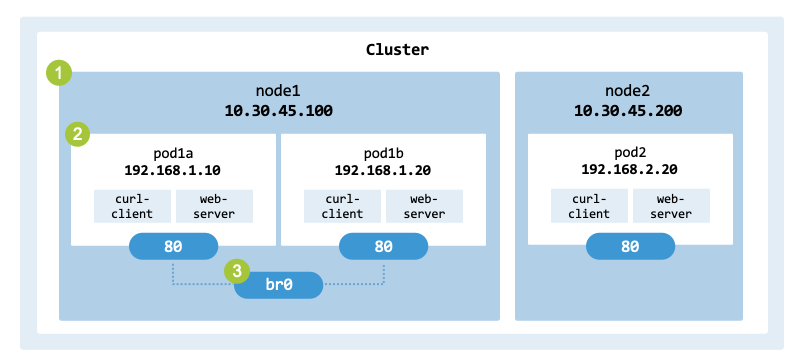
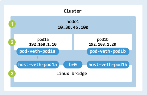
fig_pod_networking_architecture illustrates the system architecture.
The setup consists of two nodes (node1 and node2) hosting three Pods
(pod1a, pod1b, and pod2). Each Pod utilizes a sidecar pattern, containing the
following two containers:
curl-client: A lightweight container equipped with the iproute2 suite and diagnostic tools (ping, curl, nslookup, traceroute). It serves as a “Swiss Army knife” for analyzing and troubleshooting network connectivity directly from within the Pod’s network namespace.
web-server: A Python-based server that listens on port 80. It is used to demonstrate and validate internal and external HTTP traffic routing to the Pod.
Two of the Pods are connected via the Linux Bridge br0.
Architecture of the pseudo-Pods to build.#
Specification#
lst_deployment_yaml shows the deployment YAML file
(deployment.yaml) corresponding to the
architecture in fig_pod_networking_architecture. The configuration
implements a sidecar pattern, where two containers share a single network
namespace and lifecycle.
Replicas: The deployment maintains three Pod replicas across the cluster.
Containers: Each Pod consists of two containers: curl-client (for diagnostics) and web-server (for service delivery).
Images:
curl-client uses a comprehensive networking image (e.g., nicolaka/netshoot) to provide the necessary tools for troubleshooting.
web-server uses python:3.9-slim to host the application logic.
apiVersion: apps/v1
kind: Deployment
metadata:
  name: cs-deployment
spec:
  replicas: 3
  selector:
    matchLabels:
      app: cs-pod
  template:
    metadata:
      labels:
        app: cs-pod
        role: frontend
    spec:
      containers:
        - name: curl-client
          image: 'nicolaka/netshoot'
          command:
            - /bin/sh
            - -c
            - while true; do sleep 3600; done
          securityContext:
            capabilities:
              add:
                - NET_RAW
          resources:
            requests:
              cpu: 100m
              memory: 100Mi
            limits:
              cpu: 200m
              memory: 200Mi
        - name: web-server
          image: 'python:3.9-slim'
          command:
            - /bin/sh
            - -c
            - |
              echo "Python web-server" > index.html
              python3 -m http.server 80
          ports:
            - containerPort: 80
          resources:
            requests:
              cpu: 100m
              memory: 100Mi
            limits:
              cpu: 200m
              memory: 200Mi
Both containers define resources for CPU and memory. The request (guaranteed capacity) is 100m CPU and 100Mi memory, while the limit (maximum burst capacity) is 200m and 200Mi respectively.
$ kubectl apply -f deployment.yaml

deployment.apps/cs-deployment created
When you execute kubectl apply, the Kubernetes Control Plane schedules the workload. The Kubelet on the target node interacts with the Container Network Interface to configure the Pod’s networking and the Container Runtime Interface to pull images and start the containers via the underlying runtime (e.g., containerd).
Objectives#
The running example Pod ties Kubernetes networking to core Linux primitives, container networking, and the container runtime. It demonstrates several important concepts:
Linux primitives such as namespaces enable process isolation by separating kernel resources (e.g., PIDs, networks, inter-process communication, and mount points). Control groups enable the allocation and limitation of system resources—such as CPU, memory, disk I/O, and network bandwidth—for processes.
Container networking uses network namespaces to isolate resources while allowing multiple containers to share a single IP address and communicate via localhost. To connect these isolated environments to the host, veth pairs are used as virtual Ethernet cables, and Linux Bridges manage traffic between multiple Pods.
Container runtimes are responsible for managing containers on a host system, typically handling the creation, execution, and deletion of containers. Modern runtimes employ tools like containerd to implement the architecture of Kubernetes Pods by managing shared namespaces across multiple containers.
Linux Primitives#
Linux primitives such as namespaces, cgroups, and bridges are key technologies for containerization and Kubernetes networking.
Namespaces#
Namespaces (man page)
provide process isolation and virtualization of various system resources. They
allow processes to have their own isolated view of system resources.
linux-namespaces-types shows the most relevant namespaces, which
include network interfaces, process IDs, mount points, users, and
inter-process communication.
Namespace |
Description |
|---|---|
Network |
Provides an isolated network stack (e.g., interfaces, routing, and IP addresses). |
Process (PID) |
Provides an isolated process ID space, allowing processes to have PID 1 within their own namespace. |
Mount |
Enables namespaces to have their own isolated filesystem (e.g., mount points). |
User |
Isolates user IDs and group IDs inside a namespace. |
IPC |
Provides isolation of inter-process communication mechanisms (e.g., shared memory and message queues). |
UTS |
Provides a Unix Timesharing System and isolates the hostname and NIS domain name. |
Cgroup |
Isolates control group (cgroup) hierarchies to limit and monitor resource usage (e.g., CPU or memory). |
Time |
Allows processes to have different system clocks. |
In Kubernetes, the network namespace is the most critical for networking
because it allows all containers within a Pod to communicate via localhost.
By default, a Pod is a group of containers that share the network, UTS, and
IPC namespaces to act as a single logical host. However, containers do not
share the PID namespace by default; this must be enabled using the
shareProcessNamespace: true setting in the Pod spec.
fig_container_namespaces illustrates the use of namespaces within
a Pod.
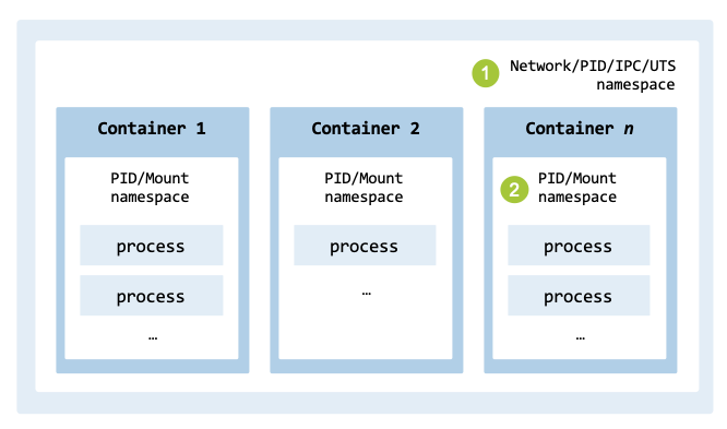
Namespaces used by containers and within a Pod.#
Information on namespaces for processes is available in the /proc filesystem. For example, the namespaces for PID 1 can be displayed with the following command:
$ sudo ls -l /proc/1/ns

total 0
lrwxrwxrwx 1 root root 0 Jun 11 08:04 cgroup -> 'cgroup:[4026531835]'
lrwxrwxrwx 1 root root 0 Jun 14 16:21 ipc -> 'ipc:[4026531839]'
lrwxrwxrwx 1 root root 0 Jun 11 08:04 mnt -> 'mnt:[4026531841]'
lrwxrwxrwx 1 root root 0 Jun 14 16:21 net -> 'net:[4026531840]'
lrwxrwxrwx 1 root root 0 Jun 14 16:21 pid -> 'pid:[4026531836]'
lrwxrwxrwx 1 root root 0 Jun 14 16:22 pid_for_children -> 'pid:[4026531836]'
lrwxrwxrwx 1 root root 0 Jun 14 16:22 time -> 'time:[4026531834]'
lrwxrwxrwx 1 root root 0 Jun 14 16:22 time_for_children -> 'time:[4026531834]'
lrwxrwxrwx 1 root root 0 Jun 14 16:21 user -> 'user:[4026531837]'
lrwxrwxrwx 1 root root 0 Jun 14 16:21 uts -> 'uts:[4026531838]'
The most relevant type of namespace for Kubernetes networking is the net
namespace. The fourth line in the output above points to this namespace,
which isolates the network stack. Additionally, the cgroup namespace
(first line) is used to isolate resource limitations and monitoring for the process.
Network namespaces#
Containers use network namespaces to isolate the network stack of each
container. They provide isolation of networking resources, such as network
devices, IP protocol stacks, routing tables, firewall rules, and Virtual Ethernet pairs.
tbl_linux_network_namespaces describes the most important elements
isolated when using network namespaces.
Components |
Description |
|---|---|
Network interfaces |
A dedicated loopback interface (lo) and other network devices (e.g., eth0) are local to each namespace. |
IP addresses |
The same IP address can be assigned to different interfaces in separate namespaces without conflict. |
Routing tables |
Each namespace maintains its own routing table, including the default gateway, static routes, and routing rules. |
Security policies |
Packet filtering and NAT rules (managed by tools such as iptables or nftables) are isolated per namespace. |
Network namespaces are typically managed using the ip tool (from the iproute2 package). It is the primary Linux utility for managing network interfaces, routing, tunnels, and namespaces. The netns object allows you to create, delete, and list network namespaces, as well as execute commands inside a specific namespace.
The command sudo ip netns add <namespace_name> creates a persistent
namespace by adding a bind mount in the /var/run/netns/ directory.
The name must be unique.
$ POD_NS="pod1a"
$ sudo ip netns add "$POD_NS"
$ sudo ip netns list

pod1a (id: 0)
The last command lists all network namespaces currently managed by the system.
Control groups#
Control groups (Wikipedia) enable the management of system resource usage. Cgroups provide fine-grained management capabilities for limiting, denying, and monitoring system resources. They were integrated into the Linux kernel with the release of version 2.6.24 in 2008.
In Kubernetes, resource requirements (e.g., memory, CPU, disk I/O, and network bandwidth) are defined in a Pod specification. The scope of the limits is set at the Pod and container level. For a detailed description, refer to Resource Management for Pods and Containers.
The Container Runtime Interface provides a programming interface that allows
the kubelet to instruct the container runtime to set the required limits
for a container. For example, if the web-server container from our running
example (lst_deployment_resources) uses too much memory, it will be
terminated.
        - name: web-server
          image: 'python:3.9-slim'
          command:
            - /bin/sh
            - -c
            - |
              echo "Python web-server" > index.html
              python3 -m http.server 80
          ports:
            - containerPort: 80
          resources:
            requests:
              cpu: 100m
              memory: 100Mi
            limits:
              cpu: 200m
              memory: 200Mi
When a Pod is assigned to a worker node, the kubelet transfers the information to the container runtime via the CRI, which translates it to an OpenContainers Runtime Spec Config that describes the container to create. This detailed specification is sent to the container runtime. If the system is configured with the systemd cgroup driver, the runtime instructs systemd to set the limits in cgroupfs files.
tbl_cgroups_pseudo_pod provides the mapping between a Pod’s resource
limits and the names of cgroup variables used to control CPU and memory
resources in Linux.
Resource |
Request |
Cgroups (v2) |
Limit |
Cgroups (v2) |
|---|---|---|---|---|
CPU |
100m |
cpu.weight |
200m |
cpu.max |
Memory |
100Mi |
memory.low |
200Mi |
memory.max |
The CPU request maps to cpu.weight, the CPU limit maps to cpu.max, the
memory request maps to memory.low, and the memory usage hard limit maps to
memory.max. The complete list of variables is described in the documentation
on the design, interface, and conventions of
Control Group v2.
While Kubernetes does not natively support limits for network bandwidth in the
Pod spec, the CNI plugin is responsible for implementing these requirements.
To specify network limits, the CNI typically uses Linux Traffic Control (tc) to
implement bandwidth shaping.
fig_pod_architecturex illustrates theaArchitecture of the Pod of the
running example.
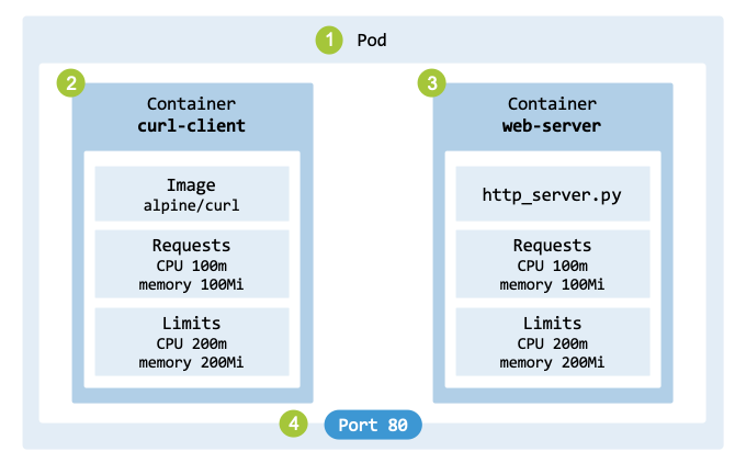
Architecture of a Pod of the running example.#
Systemd is responsible for managing cgroups at the system level when the systemd driver is used. It persists information about resource limits in virtual files within the cgroup filesystem, which is usually mounted at /sys/fs/cgroup/. Kubernetes’s cgroups are located in the kubepods.slice/ subdirectory, which contains subdirectories for each Pod and container. The command lscgroup shows the cgroups on a Linux system and their paths.
Let’s find out which worker node the Pods are running on:
$ kubectl get pods -o wide -l app=cs-pod
NAME                            STATUS   IP           NODE  ...
cs-deployment-6f5d8485c-abc12   Running  10.244.1.5   worker0
cs-deployment-6f5d8485c-def34   Running  10.244.2.8   worker1
cs-deployment-6f5d8485c-ghi56   Running  10.244.1.9   worker0
Log in to one of the nodes, and execute the command lscgroup:
$ lscgroup

...
cpuset,cpu,io,memory,hugetlb,pids,rdma,misc:/kubepods.slice/...
...
Kubernetes limits are located under the directory /sys/fs/cgroup/kubepods.slice/… and stored in a subdirectory named after the container ID. Let’s retrieve the ID of the container web-server:
$ kubectl get pod cs-deployment-6f5d8485c-abc12 \
    -o jsonpath='
        {range .status.containerStatuses[*]}
        {.name}: {.containerID}{"\n"}
        {end}
    '

net-utils: containerd://f30fd98cf38f98ab50ea495...
web-server: containerd://00004a061dee164b1f8910...
To identify the cgroup path for the container, execute:
$ lscgroup | grep 00004a061dee164b1f8910...
Since resource requirements are stored in files with names that match cgroup variables, such as cpu.max and memory.max, let’s inspect the contents of the memory.max file:
$ cd /sys/fs/cgroup/<path_to_container_cgroup>
$ cat memory.max

209715200
The file contains the number 209715200, which translates to 200MiB of memory as initially defined in the Pod specification.
Hands-on approach: To better understand how Kubernetes implements resource limits within its pods, this section explains how to create a cgroup v2 and associate it with a command to limit memory usage. This provides insight into how the Linux kernel enforces resource constraints.
Let’s start by creating a new cgroup named web-server and setting a memory limit. The first command creates the necessary configuration files within the /sys/fs/cgroup/ hierarchy. The second command sets a maximum limit of 10 MiB (10,485,760 bytes).
$ sudo mkdir -p /sys/fs/cgroup/web-server
$ echo $((10 * 1024 * 1024)) \
    | sudo tee /sys/fs/cgroup/web-server/memory.max
Next, add the current shell process to the cgroup. The memory limit will now apply to this shell and any child processes it spawns. We can verify the current memory usage (in bytes) using memory.current.
$ echo $$ | sudo tee /sys/fs/cgroup/web-server/cgroup.procs
$ cat /sys/fs/cgroup/web-server/memory.current

# Example output
503808
To test the limit, we run a Python command that allocates memory in 1 M B increments.
for i in $(seq 1 15); do
   python3 -c "a = ' ' * ($i * 1024**2); print('Allocated $i MB')"
done

Allocated 1 MB
...
Allocated 9 MB
Allocated 10 MB
Killed
The iterations successfully allocated memory until the cumulative limit was exceeded. At that point, the kernel’s Out-of-Memory (OOM) killer terminated the process. To clean up, we must move the shell back to the root cgroup before the directory can be removed; otherwise, the device will remain “busy.”
$ echo $$ | sudo tee /sys/fs/cgroup/cgroup.procs
$ sudo rmdir /sys/fs/cgroup/web-server/
By writing the PID of the current shell into the file cgroup.procs, the kernel instantly moves that process into that specific group.
Linux Bridge#
In practice, it is possible to connect two network namespaces to form a network for communication, albeit a very small one. Let us see how this can be done. We start by creating two network namespaces:
$ sudo ip netns add pod-ns1
$ sudo ip netns add pod-ns2
These two network namespaces can be connected to each other using a veth (Virtual Ethernet) pair. It corresponds to a physical Ethernet cable and provides a connection between two network interfaces. One end of the virtual pair is placed in namespace pod-ns1 (veth0) and the other in namespace pod-ns2 (veth1).
$ sudo ip link add veth0 type veth peer name veth1
$ sudo ip link set veth0 netns pod-ns1
$ sudo ip link set veth1 netns pod-ns2
The (id: 2) and (id: 3) are the NSIDs (Namespace IDs) assigned by the kernel:
$ sudo ip netns list

pod-ns2 (id: 3)
pod-ns1 (id: 2)
To configure the interfaces, an IP address (e.g., 10.0.0.1/24) is assigned to the interface veth0 within the network namespace pod-ns1, and the interface is activated. It is also a best practice to bring up the loopback interface. Similar commands are executed for pod-ns2.
$ sudo ip netns exec pod-ns1 ip addr add 10.0.0.1/24 dev veth0
$ sudo ip netns exec pod-ns1 ip link set veth0 up
$ sudo ip netns exec pod-ns1 ip link set lo up
$ sudo ip netns exec pod-ns2 ip addr add 10.0.0.2/24 dev veth1
$ sudo ip netns exec pod-ns2 ip link set veth1 up
$ sudo ip netns exec pod-ns2 ip link set lo up
To test the network connectivity from within network namespace pod-ns1 to the IP address 10.0.0.2 of network namespace pod-ns2:
$ sudo ip netns exec pod-ns1 ping 10.0.0.2 -c 3

PING 10.0.0.2 (10.0.0.2) 56(84) bytes of data.
64 bytes from 10.0.0.2: icmp_seq=1 ttl=64 time=0.024 ms
64 bytes from 10.0.0.2: icmp_seq=2 ttl=64 time=0.024 ms
64 bytes from 10.0.0.2: icmp_seq=3 ttl=64 time=0.033 ms

--- 10.0.0.2 ping statistics ---
3 packets transmitted, 3 received, 0% packet loss, time 2050ms
rtt min/avg/max/mdev = 0.024/0.027/0.033/0.004 ms
In production systems, to route traffic between namespaces across different physical hosts, encapsulation mechanisms such as GRE, VXLAN, and IP-in-IP are required. These more advanced technologies are discussed in Chapter Cluster Networking.
To locally connect multiple network interfaces across different namespaces, a
virtual switch or bridge is generally used. The Linux Bridge interface
(fig_linux_bridge) allows one to create Layer 2 (Ethernet) networks
on a single host. A bridge operates like a physical network switch between
network interfaces on a host. It is often used to create a virtual network to
support virtualization (KVM, Xen) and containerization environments (Docker, LXC).
Linux Bridge interface.#
It can forward Ethernet frames based on their MAC addresses. In simple terms, a bridge manages a MAC Address Table that records the port number where each MAC address is found. When a frame is received by the bridge, it looks up the destination MAC address in the table and forwards the frame to the matching port.
Linux Bridges are connected to network namespaces using veth pairs. As already discussed, veth devices are local Ethernet tunnels created in pairs. Packets sent to one device are immediately received by the other device. One end of the pair is attached to the Pod’s namespace and the other end is attached to the node’s network namespace.
When a Pod, container, or VM sends packets, they are routed to its veth interface; then they are transferred to the veth interface on the node to enter the bridge. The bridge then decides where to forward the packets using the MAC address table. From the node, the packets can be forwarded to a physical interface or another veth connected to a Pod, container, or VM. For broadcast and multicast, such as ARP requests, packets are sent to all ports connected to the bridge.
Container Networking#
To demonstrate multi-container Pods, this section creates a shared network namespace, sets up virtual network interfaces for the containers, and assigns an IP address to the Pod. This section also describes how several local Pods can be connected using a Linux Bridge.
The create_namespace() function (from the script pod_manager.sh)
creates an isolated networking environment generally used by container and
virtualization setups.
By leveraging a custom network namespace and veth pair, this environment
closely resembles Kubernetes’ internal networking for Pods.
create_namespace() {

    echo "Creating network namespace: $POD_NS"
    sudo ip netns del "$POD_NS" 2>/dev/null || true
    sudo ip netns add "$POD_NS"

    echo "Sleeping to enable the namespace to be created"
    sleep 1

    echo "Creating veth pair: $HOST_VETH <-> $POD_VETH"
    sudo ip link add "$HOST_VETH" type veth peer name "$POD_VETH"

    echo "Moving $POD_VETH to namespace $POD_NS"
    sudo ip link set "$POD_VETH" netns "$POD_NS"

    echo "Assigning IP to $HOST_VETH on host: $HOST_CIDR"
    sudo ip addr add "$HOST_CIDR" dev "$HOST_VETH"
    sudo ip link set "$HOST_VETH" up

    echo "Assigning IP to $POD_VETH in namespace: $POD_CIDR"
    sudo ip netns exec "$POD_NS" ip addr add "$POD_CIDR" dev "$POD_VETH"
    sudo ip netns exec "$POD_NS" ip link set "$POD_VETH" up
    sudo ip netns exec "$POD_NS" ip link set lo up

    echo "Adding default route: $HOST_IP"
    sudo ip netns exec $POD_NS ip route add default via $HOST_IP
}
The functions setup_bridge() and connect_pod() from the script
bridge_manager.sh create a Linux Bridge
to which Pods connect.
Virtual interfaces#
Kubernetes assigns a virtual Ethernet interface (veth) to the Pod, connecting
it to the underlying network through the CNI. Containers share the same veth
pair because they share the Pod’s network namespace. Linux networking provides
several technologies for creating virtual network interfaces (tbl_network_interface_types),
most notably tun, tap, and veth. These primitives allow for the creation
of software bridges such as docker0 or virbr0.
Name |
Layer |
Technology |
Use Case |
|---|---|---|---|
tun |
L3 |
Network Tunnel |
VPNs and IP-only routing |
tap |
L2 |
Universal TUN/TAP |
Connecting VM NICs to the host |
veth |
L2 |
Virtual Ethernet Device |
Connecting containers to a bridge/namespace |
While we will use a veth, this section provides examples of the use of tun and tap interfaces.
A TUN (Network Tunnel) interface is a virtual network kernel device used to tunnel IP packets at the network layer (Layer 3). It is generally used to route packets from a virtual interface to a user-space program and to encapsulate packets in VPNs. It only passes routable IPv4 packets (and IPv6 when supported). The following command creates a new network tunneling interface in Linux named tun0.
$ sudo ip tuntap add dev tun0 mode tun
$ sudo ip addr add 192.168.2.1/24 dev tun0
$ sudo ip link set dev tun0 up
$ sudo ip addr show tun0

5: tun0: <NO-CARRIER,POINTOPOINT,MULTICAST,NOARP,UP> mtu 1500 ...
link/none
inet 192.168.2.1/24 scope global tun0
   valid_lft forever preferred_lft forever
When the address is added to the interface, a corresponding route for the 192.168.2.0/24 subnet is created in the local routing table.
$ route

Kernel IP routing table
Destination   Gateway    Genmask         Flags Metric Ref  Use Iface
default       _gateway   0.0.0.0         UG    100    0      0 enp0s1
192.168.2.0   0.0.0.0    255.255.255.0   U     0      0      0 tun0
A TAP (Network Tap) is a virtual network kernel device used to capture Ethernet frames at the data link layer (Layer 2). It passes raw frames, including IPv4/IPv6, NetWare IPX, and AppleTalk. The first command creates a TAP interface named tap0, while the second activates the interface.
$ sudo ip tuntap add dev tap0 mode tap
$ sudo ip link set dev tap0 up
$ sudo ip addr show tap0

5: tap0: <NO-CARRIER,BROADCAST,MULTICAST,UP> mtu 1500 qdisc pfifo_fast
      state DOWN group default qlen 1000
    link/ether ce:77:9c:af:61:68 brd ff:ff:ff:ff:ff:ff
A veth (Virtual Ethernet Device) is a pair of virtual network interfaces that act as a virtual Ethernet cable connecting two network namespaces. These interfaces are used to connect containers to the host or to each other. Veth devices operate at Layer 2 (Ethernet) to facilitate the transport of Layer 3 (IP) traffic.
The function create_namespace() creates a veth pair and then moves one end of that pair into a specified network namespace. This operation connects a container’s isolated network stack to the host’s network stack to enable host-to-pod communication.
echo "Creating veth pair: $HOST_VETH <-> $POD_VETH"
sudo ip link add "$HOST_VETH" type veth peer name "$POD_VETH"

echo "Moving $POD_VETH to namespace $POD_NS"
sudo ip link set "$POD_VETH" netns "$POD_NS"
On the host side, the interface $HOST_VETH is assigned the IP $HOST_IP. Inside the namespace, the interface $POD_VETH is assigned the IP $POD_IP. Traffic can flow between the host and the namespace via this virtual link. The following command describes the $HOST_VETH interface from the host’s perspective:
$ HOST_VETH="host-veth-pod1a"
$ sudo ip link show "$HOST_VETH"

7: host-veth-pod1a@if3: <BROADCAST,MULTICAST,UP,LOWER_UP> mtu 1500 ...
    link/ether fa:51:51:72:c6:52 brd ... link-netns pod1a...
The next step is to assign an IP address to the host side of the veth and to the interface inside the namespace.
IP address#
The following commands assign an IP address (192.168.1.1/24) to the host-side interface of the veth pair and bring the interface up.
$ HOST_IP="192.168.1.1/24"
$ HOST_VETH="host-veth-pod1a"
$ sudo ip addr add "$HOST_IP" dev "$HOST_VETH"
$ sudo ip link set "$HOST_VETH" up
To confirm the host has successfully claimed the IP address, you can ping the local interface. Note that this test only verifies the local stack and does not traverse the veth link yet:
$ ping 192.168.1.1 -c 2

PING 192.168.1.1 (192.168.1.1) 56(84) bytes of data.
64 bytes from 192.168.1.1: icmp_seq=1 ttl=64 time=0.016 ms
64 bytes from 192.168.1.1: icmp_seq=2 ttl=64 time=0.025 ms

--- 192.168.1.1 ping statistics ---
2 packets transmitted, 2 received, 0% packet loss, time 1003ms
rtt min/avg/max/mdev = 0.016/0.020/0.025/0.004 ms
The following commands transfer the pod-side interface to the namespace, assign its IP address, and activate both the virtual and loopback (lo) interfaces inside the pod1a network namespace.
$ POD_NS="pod1a"
$ POD_IP="192.168.1.10/24"
$ POD_VETH="pod-veth-pod1a"
$ sudo ip link set "$POD_VETH" netns "$POD_NS"
$ sudo ip netns exec "$POD_NS" ip addr add "$POD_IP" dev "$POD_VETH"
$ sudo ip netns exec "$POD_NS" ip link set "$POD_VETH" up
$ sudo ip netns exec "$POD_NS" ip link set lo up
To verify end-to-end connectivity, ping the Pod’s IP address from the host. This forces the packet to travel through the $HOST_VETH and emerge at the $POD_VETH inside the namespace:
$ ping 192.168.1.10 -c 1

PING 192.168.1.10 (192.168.1.10) 56(84) bytes of data.
64 bytes from 192.168.1.10: icmp_seq=1 ttl=64 time=0.028 ms

--- 192.168.1.10 ping statistics ---
1 packets transmitted, 1 received, 0% packet loss, time 0ms
rtt min/avg/max/mdev = 0.028/0.028/0.028/0.000 ms
For complete verification, ensure the Pod can reach the host by executing a ping from within the namespace:
$ sudo ip netns exec "$POD_NS" ping 192.168.1.1 -c 1
The next step is to enable the forwarding of packets between these interfaces to allow traffic to reach external networks.
Routing#
Routing defines a specific path for network traffic to follow so it can travel between isolated environments. While the host has a route to the Pod’s IP address, the Pod needs a way to communicate back to the host and external networks. A default gateway is configured inside the network namespace to direct all outgoing traffic through the host-side of the veth pair.
By adding a route that points to the host’s IP ($HOST_IP) via the $POD_VETH interface, the namespace can communicate with networks outside its own isolated environment. This ensures that traffic originating from the containers knows how to reach the host and, eventually, the internet.
echo "Adding default route: $HOST_IP"
sudo ip netns exec $POD_NS ip route add default via $HOST_IP
This connectivity can be verified using the following command:
$ POD_NS="pod1a"
$ sudo ip netns exec "$POD_NS" route

Kernel IP routing table
Destination  Gateway      Genmask         Flags  ...  Use Iface
default      192.168.1.1  0.0.0.0         UG          0 pod-veth-pod1a
192.168.1.0  0.0.0.0      255.255.255.0   U           0 pod-veth-pod1a
The 0.0.0.0 in the gateway column for the 192.168.1.0 entry indicates that no intermediate router is needed to reach that specific subnet; the operating system understands that the destination network is directly attached to the interface (pod-veth-pod1a).
While the container has an IP address, it cannot communicate with external networks. Forwarding and routing of packets are required.
While the container now has an IP and a gateway, it still cannot reach the public internet without the host performing two specific roles: forwarding and masquerading.
IP Forwarding enables the host to act as a router, passing packets between its different network interfaces (e.g., from the virtual veth to the physical eth0). In Linux, this is enabled via sysctl:
$ sudo sysctl -w net.ipv4.ip_forward=1
Many modern Linux distributions default to iptables-nft, which uses the newer nftables kernel framework. To ensure compatibility with older scripts or specific legacy requirements, we switch to the legacy binary:
$ sudo update-alternatives --set iptables /usr/sbin/iptables-legacy
IP Masquerading is required because the Pod’s internal IP address (e.g., 192.168.1.10) is not routable on the public internet. As packets leave the host, the host must replace the Pod’s source IP with its own public IP address.
The following iptables command adds a MASQUERADE rule to the POSTROUTING chain of the NAT table. It matches traffic originating from the Pod’s subnet ($SUBNET_CIDR) and translates the source IP so the traffic appears to originate from the host itself.
echo "Enabling external routing"
sudo iptables -t nat -A POSTROUTING \
   -s "$SUBNET_CIDR" ! -o "$HOST_VETH" \
   -j MASQUERADE -m comment --comment PSEUDO_POD_POSTROUTING_MASQ
The next step is to attach these individual namespaces to a central local bridge to allow inter-Pod communication.
Local bridging#
While the script pod_manager.sh can be used to create a network namespace and a unique veth pair, its use is problematic when two Pods are created and to the same subnet, for example:
pod_manager.sh create "$POD1A_NAME" "$POD1_SUBNET" \
    "$POD1A_IP" "$POD_PORT"
pod_manager.sh create "$POD1B_NAME" "$POD1_SUBNET" \
    "$POD1B_IP" "$POD_PORT"
The two network namespaces created, pod1a and pod1b, have the same IP address (192.168.1.1/24) assigned to their respective host-side veth interfaces. This occurs because the script calculates the host-side IP address (HOST_IP) based on a hardcoded last octet, regardless of the unique IP address provided for the Pod side (POD_IP).
On node1, verify this networking issue:
$ pod_manager.sh status

Container status:
 pod1a  curl-client    docker.io/alpine/curl:latest  ...
 pod1b  curl-client    docker.io/alpine/curl:latest  ...
Namespace status:
 host-veth-pod1a       192.168.1.1/24  <-> 192.168.1.10/24
 host-veth-pod1b       192.168.1.1/24  <-> 192.168.1.20/24
This creates an IP conflict in the host’s routing table. The host cannot reliably determine which veth interface to use when sending traffic to one of the namespaces.
To resolve this issue, we can:
Use a different subnet for the host-side link (e.g., 192.168.x.0/24).
Use a unique host IP within the shared network prefix (e.g., 192.168.1.1 for pod1a and 192.168.1.2 for pod1b).
Create a Linux Bridge to connect the two isolated network namespaces.
We opt for option 3 and create a Linux Bridge called br0 on node1 to connect the two Pods. The host-side veth interfaces host-veth-pod1a and host-veth-pod1b are then attached to the bridge and do not require an IP address on the host; they simply act as ports on the virtual switch. Since the bridge operates at Layer 2 (Data Link Layer), the traffic between the Pods is switched directly by the bridge, which is more efficient than routing.
The function setup_bridge() from the file bridge_manager.sh
creates and manages the Linux Bridge. The new bridge interface is created using
the ip link add command and it is named br0.
setup_bridge() {

    if ! ip link show "$BRIDGE_NAME" > /dev/null 2>&1; then
        echo "Creating bridge $BRIDGE_NAME"
        sudo ip link add name "$BRIDGE_NAME" type bridge
        sudo ip link set "$BRIDGE_NAME" up

        echo "Assigning gateway IP $HOST_CIDR to $BRIDGE_NAME"
        sudo ip addr add "$HOST_CIDR" dev "$BRIDGE_NAME"
    else
        echo "Bridge $BRIDGE_NAME already exists."
    fi
}
The bridge is now active and ready to accept other interfaces (like veth peers) as members.
$ BRIDGE_NAME="br0"
$ sudo ip link show "$BRIDGE_NAME"

22: br0: <NO-CARRIER,BROADCAST,MULTICAST,UP> mtu 1500 qdisc noqueue state DOWN mode DEFAULT group default qlen 1000
    link/ether 3e:24:1b:52:69:b1 brd ff:ff:ff:ff:ff:ff
To make the two Pods members, we connect the host-side ends of the two virtual Ethernet veth pairs to the Linux Bridge. The bridge br0 will learn the MAC addresses and forward Ethernet frames between the two virtual interfaces connected to it, host-veth-pod1a and host-veth-pod1b.
The function connect_pod() from the file bridge_manager.sh connects a Pod to the bridge br0.
setup_bridge() {

    if ! ip link show "$BRIDGE_NAME" > /dev/null 2>&1; then
        echo "Creating bridge $BRIDGE_NAME"
        sudo ip link add name "$BRIDGE_NAME" type bridge
        sudo ip link set "$BRIDGE_NAME" up

        echo "Assigning gateway IP $HOST_CIDR to $BRIDGE_NAME"
        sudo ip addr add "$HOST_CIDR" dev "$BRIDGE_NAME"
    else
        echo "Bridge $BRIDGE_NAME already exists."
    fi
}
The Pods can be connected to the bridge using the following command and parameters:
$ bridge_manager.sh connect "$POD1A_NAME" "$POD1_SUBNET" \
    "$POD1A_IP" "$BRIDGE"
$ bridge_manager.sh connect "$POD1B_NAME" "$POD1_SUBNET" \
    "$POD1B_IP" "$BRIDGE"
We can now test the communication between the two network namespaces pod1a and pod1b (192.168.1.20) using the ping command. The output shows successful communication:
$ POD1A_NAME="pod1a"
$ POD_IP="192.168.1.20"
$ sudo ip netns exec "$POD1A_NAME" ping -c 2 "$POD_IP"

PING 192.168.1.20 (192.168.1.20) 56(84) bytes of data.
64 bytes from 192.168.1.20: icmp_seq=1 ttl=64 time=0.131 ms
64 bytes from 192.168.1.20: icmp_seq=2 ttl=64 time=0.034 ms

--- 192.168.1.20 ping statistics ---
2 packets transmitted, 2 received, 0% packet loss, time 1026ms
rtt min/avg/max/mdev = 0.034/0.082/0.131/0.048 ms
When pod1a pings pod1b, the packets are encapsulated in Ethernet frames, which travel as follows:
Out of pod1a’s interface pod-veth-pod1a.
Through the veth pair into the host side interface host-veth-pod1a.
Through the bridge br0 using L2 forwarding.
Out the other port host-veth-pod1b.
Through the second veth pair into pod1b’s interface pod-veth-pod1b.
By assigning the IP address 192.168.1.1/24 to the bridge interface itself, it is possible for the host to ping the Pods or be pinged by them. The bridge acts as a router for traffic originating from or destined for the host’s main network interfaces.
The output of the ping command shows successful communication between the host and pod1a:
$ POD_IP="192.168.1.20"
$ ping -c 2 "$POD_IP"

PING 192.168.1.20 (192.168.1.20) 56(84) bytes of data.
64 bytes from 192.168.1.20: icmp_seq=1 ttl=64 time=0.106 ms
64 bytes from 192.168.1.20: icmp_seq=2 ttl=64 time=0.031 ms

--- 192.168.1.20 ping statistics ---
2 packets transmitted, 2 received, 0% packet loss, time 1035ms
rtt min/avg/max/mdev = 0.031/0.068/0.106/0.037 ms
Container Runtime#
The previous sections prepared the network plumbing between the namespaces and the host. This section explains how to assign processes to a namespace. We use two distinct methods: a netns-based approach and a container engine approach.
Netns-based container#
The netns-based approach utilizes lightweight Linux network namespaces (netns) to simulate a container inside the Pod. This method is used to launch simple, standalone processes—such as a Python HTTP server—via the ip netns exec command.
The function start_container_server() (script pod_manager.sh)
is responsible for launching a web server within the isolated network namespace
and listening on the designated IP address and port.
start_container_server() {

    echo "Starting container server: ($POD_NS, $POD_IP:$CONTAINER_PORT)"

    sudo ip netns exec "$POD_NS" \
        env POD_IP="$POD_IP" CONTAINER_PORT="$CONTAINER_PORT" \
        nohup python3 $CONTAINER_HTTP_SERVER < /dev/null > $POD_NS.$CONTAINER_HTTP_SERVER.log 2>&1 &

    echo "Container created."
}
The function starts the Python HTTP server $CONTAINER_HTTP_SERVER inside the network namespace created earlier. It uses the ip netns exec $POD_NS command to execute commands inside the isolated network namespace named $POD_NS.
The file http_server.py starts an
HTTP server. It listens on all available interfaces (including $POD_IP)
at port $CONTAINER_PORT. The server handles GET requests, returning an
HTML response that displays its own IP address and the requested path.
import http.server
import socketserver
import os

SERVER_IP = os.environ.get('POD_IP', 'Unknown_IP')
SERVER_PORT = int(os.environ.get('CONTAINER_PORT', 8000))

class CustomHandler(http.server.BaseHTTPRequestHandler):
    def do_GET(self):
        self.send_response(200)
        self.send_header("Content-type", "text/html")
        self.end_headers()

        html_content = f"""
HTTP Server IP address: {SERVER_IP}
Request path: {self.path}
"""
        self.wfile.write(bytes(html_content, "utf-8"))

def run_server():
    server_address = ('0.0.0.0', SERVER_PORT)
    httpd = socketserver.TCPServer(server_address, CustomHandler)
    print(f"Starting custom HTTP server: ({SERVER_IP}:{SERVER_PORT})")
    httpd.serve_forever()

if __name__ == "__main__":
    run_server()
Verify that the server running inside that namespace is accessible via its loopback address (127.0.0.1) using curl at http://127.0.0.1:$CONTAINER_PORT. (Note: The lo interface must be set to up within the namespace for this to work).
$ sudo ip netns exec pod1a bash -c "curl 127.0.0.1:$POD_PORT"

HTTP Server IP address: 192.168.1.10
Request path: /
Container engine#
To build the second container, we use the container engine approach. It uses the Container Runtime Interface and the container runtime containerd to retrieve and launch an image. This mirrors the real-world operation of Kubernetes Pods. Currently, containerd and CRI-O are the most widely adopted runtimes since they have close integration with Kubernetes. Historically, Docker was the preferred choice; however, starting with version 1.20, Kubernetes deprecated the “dockershim” and direct Docker support in favor of runtimes that natively implement the CRI.
The function start_container_client() is responsible for pulling a specified container image, starting the container, and attaching it to the previously created network namespace.
start_container_client() {

    echo "Pulling container image $CONTAINER_IMAGE"
    sudo ctr --namespace "$POD_NS" image pull "$CONTAINER_IMAGE"

    echo "Starting container $CONTAINER_IMAGE"
    sudo ctr --namespace $POD_NS run --detach \
        --with-ns="network:/var/run/netns/$POD_NS" \
        "$CONTAINER_IMAGE" "$CONTAINER_NAME" "$CONTAINER_COMMAND"

    echo "Container created."
}
The code pulls a container image from Docker Hub (docker.io) using the containerd CLI command ctr. The variable $CONTAINER_IMAGE references the container image name for the curl client. This ensures the required image is available locally before starting the container. The parameter –with-ns (or the equivalent configuration in your script) attaches the container’s network stack to the previously created Linux network namespace. The container runs in the background.
To verify that the container was properly configured within containerd, execute:
$ sudo ctr --namespace pod1a container list

CONTAINER      IMAGE                           RUNTIME
curl-client    docker.io/alpine/curl:latest    io.containerd.runc.v2
To verify that the container task is running:
$ sudo ctr --namespace pod1a task ls

TASK           PID     STATUS
curl-client    2457    RUNNING
To demonstrate a basic example of how to make an HTTP request from the curl-client container to the web-server container, we make a REST call to http://127.0.0.1:$CONTAINER_PORT. Since both containers share the same network namespace, they can communicate over the loopback interface.
sudo ctr --namespace pod1a task exec \
    --exec-id 1 \
    --tty "curl-client" \
    curl 127.0.0.1:80

HTTP Server IP address: 192.168.1.10
Request path: /
This example can be further customized by adding more complex logic to the client container, such as sending data to the server, handling responses, and implementing more robust error handling.
Pause container#
In Kubernetes, an infrastructure container is created for each Pod: the pause container. This container is responsible for maintaining the network namespace of a Pod. While it does not run a functional application, it ensures that all containers within the Pod can share the same network stack.
When a new Pod is created, a sandbox (the pause container) is initialized first. It has no significant workload and exists primarily to hold the namespace. All other application containers are subsequently joined to the same network namespace. If the pause container exits, the Pod’s networking environment is destroyed, and the Kubelet must restart the Pod containers to restore the sandbox.
In our running example (lst_deployment_yaml), the pause container is
created automatically by Kubernetes and is not explicitly defined in the Pod
manifest. The curl-client and web-server containers share the same network
namespace as this pause container, allowing them to communicate with each other
using the loopback interface (127.0.0.1) or the Pod’s internal IP.
To see the pause container image, execute the following command:
$ sudo crictl images

IMAGE                       TAG        IMAGE ID           SIZE
docker.io/alpine/curl       latest     f3675ce0fe26f      6.29MB
...
registry.k8s.io/pause       3.9        829e9de338bd5      268kB
To view the process hierarchy under Linux:
$ sudo ps ax --forest

...
2153110 ?  Sl  0:00 /usr/bin/containerd-shim-runc-v2 -namespace k8s.io -id ...
2153130 ?  Ss  0:00  \_ /pause
2153201 ?  Ss  0:00  \_ /bin/sh -c while true; do sleep 3600; done
2153214 ?  S   0:00  |   \_ sleep 3600
2153250 ?  Ss  0:00  \_ nginx: master process nginx -g daemon off;
2153293 ?  S   0:00      \_ nginx: worker process
2153294 ?  S   0:00      \_ nginx: worker process
The pause container (PID 2153130) holds the network namespace for the Pod. The process with PID 2153201 represents the curl-client (running a persistent loop), and the process with PID 2153250 is the main NGINX process of the web-server. Note that these application processes are siblings to the pause process, not children, but they all share the network environment initialized by PID 2153130.
We leave the integration of the pause container as an exercise for the reader.
Hands-on Implementation#
This section describes several functions to manage the Pod template defined
in the specification in lst_deployment_yaml. The code is designed
to mimic a basic networking scenario where both containers share a virtual
network interface, enabling inter-container communication.
fig_hands_on_architecture shows details of the internal structure of
the Pod. Resources and limits are not implemented, since the focus is on
networking.
The Pods to be deployed on node1 and node2 have the following
characteristics:
node1has two network namespaces calledpod1aandpod1b.node2has one network namespace calledpod2.node1’s Pod network is192.168.1.0/24, and the Pods’ IPs are192.168.1.10and192.168.1.20.node2’s Pod network is192.168.2.0/24, and the Pod IP is192.168.2.20.The node
node1has a bridge interface calledbr0that connects the Pods on that node.The Pods contain two containers: one running the
alpine/curl:latestimage and another running a Python HTTP web server.The Python HTTP server is listening on port
80.
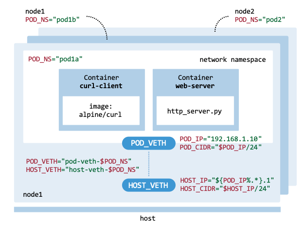
Representation of the Pods deployed.#
The cluster is deployed as follows:
Create cluster: The
hostexecutes the scriptsnode_manager.shandcluster_vars.envto initialize the infrastructure with two nodes (node1,node2).Create pods:
node1uses the scriptspod_manager.sh,node_vars.env, andcluster_vars.envto build and runpod1aandpod1b.node2uses the same scripts to build and runpod2.Create bridge:
node1uses the scriptbridge_manager.shto connect the newly created Pods’ network interfaces to a Linux Bridge.
Create cluster#
We use the script cluster_vars.env to
define the set of environment variables used to configure the deployed cluster
(such as the number of nodes, namespaces, IP addresses, and the Pod and bridge names).
#!/bin/bash

# Worker nodes
export NUM_NODES=2

# Pod Names
export POD1A_NAME="pod1a"
export POD1B_NAME="pod1b"
export POD2_NAME="pod2"

# Pod IPs
export POD1A_IP="192.168.1.10"
export POD1B_IP="192.168.1.20"
export POD2_IP="192.168.2.20"

# Pod port
export POD_PORT=80

# Network configuration
export POD1_SUBNET="192.168.1.0/24"
export POD2_SUBNET="192.168.2.0/24"
export BRIDGE_NAME="br0"
To export the variables, run the following commands in your terminal:
$ export PATH=$PATH:.
$ BOOK_DIR="/path/to/your/book/dir"
$ cd $BOOK_DIR/chapters/pod_networking/scripts
$ source cluster_vars.env
Create the two worker nodes using the script
node_manager.sh
from Chapter Kubernetes:
$ $BOOK_DIR/chapters/the_foundation/scripts/node_manager.sh create
The cluster configuration can be displayed using the status command:
$ $BOOK_DIR/chapters/the_foundation/scripts/node_manager.sh status

node1       Running       10.30.45.100     Ubuntu 24.04 LTS
node2       Running       10.30.45.200     Ubuntu 24.04 LTS

IPs/Interface: 'source ./node_vars.env'
export NODE1_IP="10.30.45.100"
export NODE2_IP="10.30.45.200"
export NODE_IFACE="ens3"
To load the node-specific variables, execute source ./node_vars.env.
Copy the necessary scripts to node1 and node2 to enable Pod creation on the remote nodes:
FILES="cluster_vars.env node_vars.env pod_manager.sh" \
"bridge_manager.sh http_server.py"
for node in node1 node2; do
    scp -o StrictHostKeyChecking=no $FILES ubuntu@$node:~/
done
Create pods#
The script pod_manager.sh contains several
functions to manage the Pod template. At the beginning of the bash script,
several environment variables are defined to configure networking and container
settings.
# Pod network configuration
POD_NS=$2
SUBNET_CIDR=$3
SUBNET_CIDR_SUFFIX="${SUBNET_CIDR#*/}"

# Virtual Ethernet (veth) devices
POD_VETH="pod-veth-$POD_NS"
POD_IP=$4
POD_CIDR="$POD_IP/$SUBNET_CIDR_SUFFIX"

HOST_VETH="host-veth-$POD_NS"
HOST_IP="${POD_IP%.*}.1"
HOST_CIDR="$HOST_IP/24"

# Container 1 (client)
CONTAINER_NAME="curl-client"
CONTAINER_IMAGE="docker.io/alpine/curl:latest"
CONTAINER_COMMAND="/bin/sh"

# Container 2 (server)
CONTAINER_HTTP_SERVER='http_server.py'
CONTAINER_PORT=$5
The POD_NS variable sets the namespace for the pods, and the SUBNET variable defines the IP address range to be used. The POD_VETH and POD_IP define the Pod’s virtual Ethernet interface and IP address, with POD_CIDR specifying the Pod’s network range. Similarly, the HOST_VETH and HOST_IP variables configure the virtual Ethernet interface and the host’s IP address, while HOST_CIDR specifies the host’s IP address in CIDR notation.
The CONTAINER_NAME and CONTAINER_IMAGE variables identify the client instance. The CONTAINER_COMMAND defines the shell to be used within the container. For the server-side configuration, CONTAINER_HTTP_SERVER references the specific Python script responsible for handling requests, while CONTAINER_PORT assigns the networking port on which the service will listen for incoming traffic.
Deployment on node1
Access node1 using ssh ubuntu@node1, which is where pod1a and pod1b will reside.
$ ssh ubuntu@node1
Set the node-specific environment variables on node1 by sourcing the node_vars.env and cluster_vars.env files:
$ export PATH=$PATH:.
$ source node_vars.env
$ source cluster_vars.env
Create and start the Pod named pod1a by setting up the Pod’s network namespace and running the simple HTTP server inside it. Make sure the Bash script pod_manager.sh and the Python script http_server.py are available on node1.
$ pod_manager.sh create $POD1A_NAME $POD1_SUBNET $POD1A_IP $POD_PORT

Creating network namespace: pod1a
Creating veth pair: host-veth-pod1a <-> pod-veth-pod1a
Assigning IP to host-veth-pod1a on host: 192.168.1.1/24
Moving pod-veth-pod1a to namespace pod1a
...
Pod setup complete. Containers are running in the shared namespace.
Also create and start the Pod named pod1b:
$ pod_manager.sh create $POD1B_NAME $POD1_SUBNET $POD1B_IP $POD_PORT
Verify the status of the Pods after creation. The function status() displays the running containers created using sudo ctr container ls. It also examines host-side virtual Ethernet (veth) interfaces named host-veth- to identify and report their network connectivity, displaying IP addresses for both the host side and the corresponding Pod side.
$ pod_manager.sh status

Container status:
 pod1a  curl-client    docker.io/alpine/curl:latest    io.containerd.runc.v2
 pod1b  curl-client    docker.io/alpine/curl:latest    io.containerd.runc.v2
Namespace status:
 host-veth-pod1a       192.168.1.1/24  <-> 192.168.1.10/24
 host-veth-pod1b       192.168.1.2/24  <-> 192.168.1.20/24
Test the service running inside pod1a and pod1b using the test option of pod_manager.sh. For pod1a, attempt to connect to the Pod’s IP address (192.168.1.10) on port 80 to verify that the Python HTTP server is responding correctly.
$ pod_manager.sh test $POD1A_NAME $POD1_SUBNET $POD1A_IP $POD_PORT

Making REST call from container curl-client to container 192.168.1.10:80

HTTP Server IP address: 192.168.1.10
Request path: /
Deployment on node2
Access node2 using ssh ubuntu@node2, which is where pod2 will reside.
$ ssh ubuntu@node2
Set the node-specific variables on node2 by sourcing the environment files:
$ export PATH=$PATH:.
$ source node_vars.env
$ source cluster_vars.env
Create and start the Pod named pod2.
$ pod_manager.sh create $POD2_NAME $POD2_SUBNET $POD2_IP $POD_PORT

Creating network namespace: pod2
Creating veth pair: host-veth-pod2 <-> pod-veth-pod2
Assigning IP to host-veth-pod2 on host: 192.168.2.1/24
Moving pod-veth-pod2 to namespace pod2
...
Pod setup complete. Containers are running in the shared namespace.
Verify the status of the Pod after creation.
$ pod_manager.sh status

Container status:
 pod2   curl-client    docker.io/alpine/curl:latest    io.containerd.runc.v2
Namespace status:
 host-veth-pod2        192.168.2.1/24  <-> 192.168.2.20/24
Test Pod pod2:
$ pod_manager.sh test $POD2_NAME $POD2_SUBNET $POD2_IP $POD_PORT

Making REST call from container curl-client to container 192.168.2.20:80

HTTP Server IP address: 192.168.2.20
Request path: /
Create bridge#
The script bridge_manager.sh is
responsible for creating the bridge and connecting the Pods to it. A Pod is
connected using a virtual Ethernet (veth) pair: one end remains in the Pod’s
network namespace and the other end is attached to the host’s bridge, br0.
This setup allows the Pod to communicate with other Pods on the same bridge
and with external networks.
On node1, connect pod1a to the virtual network bridge:
$ bridge_manager.sh connect $POD1A_NAME $POD1_SUBNET $POD1A_IP $BRIDGE

Creating bridge br0
Assigning gateway IP 192.168.1.1/24 to br0
Connecting to Pod pod1a.
Removing IP address 192.168.1.1/24 from from the veth interface.
Plugging virtual cable into the bridge.
Set default route via the bridge gateway.
Pod connected.
Execute similar commands to connect the network interface of pod1b to the bridge br0:
$ bridge_manager.sh connect $POD1B_NAME $POD1_SUBNET $POD1B_IP $BRIDGE
Query the bridge state after connecting pod1a and pod1b and verify that:
The virtual bridge interface br0 is up (state UP) and has been assigned the gateway IP address of the Pod subnet, 192.168.1.1/24. This acts as the default gateway for all Pods connected to it.
An interface named host-veth-pod1a is shown as UP and attached to master br0, confirming that the host side of the veth pair for pod1a is successfully bridged.
An interface named host-veth-pod1b shows similar output.
$ bridge_manager.sh status

70: br0: <BROADCAST,MULTICAST,UP,LOWER_UP> mtu 1500 qdisc noqueue ...
    link/ether 4e:4b:eb:1a:d8:c1 brd ff:ff:ff:ff:ff:ff
    inet 192.168.1.1/24 scope global br0
    valid_lft forever preferred_lft forever
    inet6 fe80::4c4b:ebff:fe1a:d8c1/64 scope link
    valid_lft forever preferred_lft forever
69: host-veth-pod1a@if68: <BROADCAST,MULTICAST,UP,LOWER_UP> ...
72: host-veth-pod1b@if71: <BROADCAST,MULTICAST,UP,LOWER_UP> ...
With the Python HTTP server running inside the Pods, verify that $POD1A_IP:$POD_PORT is reachable and responding correctly:
$ curl $POD1A_IP:$POD_PORT

HTTP Server IP address: 192.168.1.10
Request path: /
Verify that you can also connect to $POD1B_IP:$POD_PORT.
Teardown cluster#
To tear down the entire networking stack and all workloads on the first node, execute the following commands on node1:
$ pod_manager.sh delete $POD1A_NAME $POD1_SUBNET $POD1A_IP
$ pod_manager.sh delete $POD1B_NAME $POD1_SUBNET $POD1B_IP
$ bridge_manager.sh delete $POD1A_NAME $POD1_SUBNET $POD1A_IP
The pod_manager.sh commands remove Pods pod1a and pod1b and clean up their associated virtual interfaces and namespaces. Afterwards, call bridge_manager.sh to remove the Linux Bridge br0 that connected the Pods.
To clean up the second node, execute the following commands on node2:
$ pod_manager.sh delete $POD2_NAME $POD2_SUBNET $POD2_IP