Cluster Networking#
In the previous chapter on Service Networking, we explained how to create a service using primitives such as iptables and routing. This chapter describes the technical architecture and implementation of Kubernetes cluster networking using virtual switching and overlay networks, detailing how Container Network Interface (CNI) plugins enable communication between Pods across different hosts by utilizing Linux Bridges, Open vSwitch (OVS), and Virtual eXtensible LAN (VXLAN) tunnels. The chapter provides an in-depth look at the CNI specification, outlining the lifecycle of Pod network creation and the execution commands required for managing network namespaces. Furthermore, it offers a hands-on demonstration for building a custom CNI plugin using Bash, covering essential tasks such as IP address management (IPAM), routing configuration, and NAT setup via iptables.
Running example#
In Kubernetes production environments, Pods are generally distributed across multiple worker nodes within a cluster. These nodes can even span different geographical locations or data centers. This multi-host, potentially multi-network environment requires routing data packets between Pods regardless of which node they are running on.
The primary virtual networking technologies used for cross-node communication can be categorized into two main groups: virtual switching and overlay networks.
Virtual switching, such as Linux Bridge and OVS, are used locally on each node to manage Pod-to-Pod communication on the same node and to connect Pod interfaces to the overlay network.
Overlay networks, such as VXLAN, GRE, and IP-in-IP, are used to route Pod traffic between nodes over the underlying physical network. They encapsulate the original Layer 2 (Ethernet) or Layer 3 (IP) Pod traffic inside an external packet that can be routed over the underlying physical network.
In Kubernetes, cross-node networking is accomplished using a CNI plugin that
implements an overlay network (e.g., Flannel or Calico) using technologies
like Linux Bridge, Open vSwitch, and VXLAN.
tbl-bridge-ovs-vxlan summarizes popular CNI plugins and their use
of virtual networking components.
The CNI plugin is responsible for tracking the IP address of each Pod on its
respective node and moving network packets between nodes to ensure that
Pod-to-Pod communication works cluster-wide.
CNI Plugin |
Linux Bridge |
Open vSwitch |
VXLAN |
|---|---|---|---|
Yes |
No |
No |
|
No |
Yes |
Yes |
|
No |
No |
Yes |
|
Yes |
No |
Yes |
While some of these plugins support alternative modes—such as Calico’s native, unencapsulated Layer 3 routing via BGP—this table specifically analyzes their behavior when using the virtual switching and overlay technologies discussed in this chapter.
Architecture#
The architecture shown in cluster_networking_arch is built around two
nodes, each with a Linux Bridge.
Each bridge is connected to containers (which simulate a Pod).
The core feature is that these two Linux Bridges, residing on separate hosts,
are connected using a VXLAN tunnel over a Layer 3 underlay network (such as
a private routed network or VPC).
This setup allows containers, even though they are physically separated, to
communicate directly using their private IP addresses, simulating a single L2
network segment.
Testbed used to verify the capabilities of the CNI Bash plugin.#
Objectives#
The main objectives of this chapter are to:
Communication: Explain how Linux Bridges, OVS, and VXLAN tunnels can be used to extend Layer 2 network segments across different Kubernetes nodes.
CNI: Introduce the CNI specification as the standard for configuring Pod networking.
CNI plugins: Provide a guide for developing and deploying a custom CNI plugin to manage the lifecycle of Pod network configurations.
Linux primitives#
Open vSwitch#
While the Linux Bridge (discussed in the chapter on Pod Networking)
offers a straightforward way to connect Pods, virtual machines, or containers,
Open vSwitch (OVS) is built for high-scale, programmable network environments.
As outlined in linux_bridge_vs_ovs, the choice between them often
depends on whether simplicity or advanced Software-Defined Networking (SDN)
capabilities are required.
Feature |
Linux Bridge |
Open vSwitch (OVS) |
|---|---|---|
Complexity |
Simple; native to the kernel. |
Higher (requires daemons and databases). |
Tools |
|
|
Performance |
Low overhead for standard kernel L2 routing. |
High throughput via DPDK or kernel flow caching. |
Features |
Basic L2 forwarding, VLAN tagging. |
OpenFlow, ACLs, hardware offloading. |
Programmability |
Limited; manual configuration. |
High; supports OpenFlow and SDN. |
Use Cases |
Simple setups. |
Cloud environments (e.g., OpenStack). |
OpenStack was one of the most relevant system to adopt Open vSwitch as a more robust alternative to the default Linux Bridge. In that ecosystem, it functioned within the hypervisor to connect virtual machines. In containerized environments, OVS fulfills a similar role directly on the container host/worker node to connect Pods. Its integration with OpenStack Neutron enabled the platform to deliver advanced networking services, such as complex tunneling and software-defined traffic management.
In this section, we demonstrate how to configure an Open vSwitch bridge to enable
Pods to communicate.
As illustrated in ovs_bridge, the bridge interface functions in a similar
way to a Linux Bridge but offers enhanced scalability and control.
Open vSwitch bridge to enable Pods to communicate.#
To implement this setup, we will follow a five-step process:
Provision the node: Set up a clean environment using Multipass and install the required OVS and container utilities.
Create network namespaces: Initialize isolated namespaces (pod1a and pod1b) to mimic independent Pod network stacks.
Initialize the OVS bridge: Create and bring up the OVS bridge (br0).
Attach Pods to the bridge: Move virtual Ethernet (veth) interface pairs into the OVS-managed switch.
Verify and clean up: Validate end-to-end connectivity via ICMP (ping) and tear down the temporary resources.”
Step 1: Create the host node (VM): Create a virtual machine named node1 using Multipass to serve as our cluster node, and install containerd.
multipass delete node1 --purge 2>/dev/null || true
multipass launch 24.04 --name node1 --cpus 1 --memory 1G --disk 10G
multipass exec node1 -- bash \
    -c "sudo apt update && sudo apt install containerd -y"
Copy local scripts pod_manager.sh and ovs_manager.sh onto it and ensure they can be executed easily from the command line.
BOOK_DIR="/home/jcardoso/Work/git/kubernetes"
POD_NETWORKING="$BOOK_DIR/chapters/pod_networking/scripts"
CLUSTER_NETWORKING="$BOOK_DIR/chapters/cluster_networking/scripts"
multipass transfer $POD_NETWORKING/pod_manager.sh node1:.
multipass transfer $CLUSTER_NETWORKING/ovs_manager.sh node1:.
multipass exec node1 -- bash \
    -c "echo 'export PATH=\"\$PATH:.\"' >> ~/.bashrc"
Note: While including the current directory (.) in the PATH environment variable is a security risk, the testbed is a controlled environment for demonstration purposes.
Log in to node1 to create Pods and the Open vSwitch bridge.
$ multipass shell node1
Step 2: Create namespaces: Create two Pods using the pod_manager.sh script presented in Chapter Pod Networking. The Pods are created using Linux network namespaces and Virtual Ethernet (veth) pairs.
$ pod_manager.sh create pod1a 192.168.1.0/24 192.168.1.10 8080
$ pod_manager.sh create pod1b 192.168.1.0/24 192.168.1.20 8080
The two commands generate the files pod1a.env and pod1b.env, which contain the configuration details of the Pods and networks created.
$ cat pod1a.env
# Generated environment variables for pod1a
POD_NS="pod1a"
SUBNET_CIDR="192.168.1.0/24"
SUBNET_CIDR_SUFFIX="24"
POD_VETH="pod-veth-pod1a"
POD_IP="192.168.1.10"
POD_CIDR="192.168.1.10/24"
HOST_VETH="host-veth-pod1a"
HOST_IP="192.168.1.1"
HOST_CIDR="192.168.1.1/24"
CONTAINER_NAME="curl-client"
CONTAINER_IMAGE="docker.io/alpine/curl:latest"
CONTAINER_COMMAND="/bin/sh"
CONTAINER_HTTP_SERVER="http_server.py"
CONTAINER_PORT="8080"
Step 3: Create bridge:
The ovs_manager.sh script serves as a
lifecycle manager for Open vSwitch. It automates the installation of the
service and the creation of a virtual bridge.
By default, the script uses ovs-br0 as the bridge name.
You can customize this by modifying the OVS_BRIDGE_NAME variable within
the script:
OVS_BRIDGE_NAME="ovs-br0"
The script contains two primary functions to prepare the environment:
install_ovs(): Installs the openvswitch-switch package. While this script is optimized for Ubuntu, the package names may vary across different Linux distributions.setup_ovs_bridge(): Initializes the OVS bridgeovs-br0and sets the interface state to “up.”
install_ovs() {
    if ! command -v ovs-vsctl &> /dev/null; then
        echo "Open vSwitch not found. Installing on Ubuntu..."
        sudo apt-get update
        sudo apt-get install -y openvswitch-switch
        sudo systemctl enable --now openvswitch-switch
    fi
}
create_ovs_bridge() {
    echo "Creating OVS bridge $OVS_BRIDGE_NAME."
    sudo ovs-vsctl --may-exist add-br ${OVS_BRIDGE_NAME}
    sudo ip link set ${OVS_BRIDGE_NAME} up
}
Run the script to create the bridge. Upon success, the script generates a bridge.env file containing the environment variables describing the bridge.
$ ovs_manager.sh setup

...
File 'bridge.env' created successfully.
To export the bridge configuration to the current shell, source the file:
$ source bridge.env
You can verify the bridge configuration from two perspectives: the OVS database and the host operating system. Use the following command to view the internal OVS hierarchy, including ports, interface types, and the OVS version:
$ sudo ovs-vsctl show

beff5d7c-5a52-48bf-89a5-6d046ece1a8c
    Bridge ovs-br0
        Port ovs-br0
            Interface ovs-br0
                type: internal
    ovs_version: "3.3.4"
To view the bridge from the host’s perspective (to verify MAC addresses, MTU, and link state), use the ip command:
$ ip address show $OVS_BRIDGE_NAME

16: ovs-br0: <BROADCAST,MULTICAST,UP,LOWER_UP> mtu 1500 qdisc noqueue state UNKNOWN group default qlen 1000
    link/ether fa:9a:23:70:75:4c brd ff:ff:ff:ff:ff:ff
    inet6 fe80::f89a:23ff:fe70:754c/64 scope link
       valid_lft forever preferred_lft forever
Step 4: Attach Pods: Transfer the host-side virtual interface of the Pods into an Open vSwitch bridge. This step connects the network namespace to the bridge. To transition from a direct point-to-point veth connection to a bridge-based architecture, remove the IP from the host-side interface before attaching it to the bridge.
$ source pod1a.env
$ POD1A_NS="$POD_NS"
$ sudo ip addr del $HOST_CIDR dev $HOST_VETH
$ sudo ovs-vsctl add-port $OVS_BRIDGE_NAME $HOST_VETH
$ sudo ip link set $HOST_VETH up
$ source pod1b.env
$ POD1B_IP="$POD_IP"
$ sudo ip addr del $HOST_CIDR dev $HOST_VETH
$ sudo ovs-vsctl add-port $OVS_BRIDGE_NAME $HOST_VETH
$ sudo ip link set $HOST_VETH up
The output from ip a shows the virtual networking components created.
While some appear “DOWN” or “UNKNOWN,” this is generally expected behavior
within an OVS architecture.
$ ip a

...
4: host-veth-pod1a@if3: <BROADCAST,MULTICAST,UP,LOWER_UP> mtu 1500 qdisc noqueue master ovs-system state UP group default qlen 1000
    link/ether 6e:2f:c4:52:54:a7 brd ff:ff:ff:ff:ff:ff link-netns pod1a
    inet6 fe80::6c2f:c4ff:fe52:54a7/64 scope link
      valid_lft forever preferred_lft forever
6: host-veth-pod1b@if5: <BROADCAST,MULTICAST,UP,LOWER_UP> mtu 1500 qdisc noqueue master ovs-system state UP group default qlen 1000
    link/ether 0e:9b:cc:8f:56:e2 brd ff:ff:ff:ff:ff:ff link-netns pod1b
    inet6 fe80::c9b:ccff:fe8f:56e2/64 scope link
      valid_lft forever preferred_lft forever
11: ovs-system: <BROADCAST,MULTICAST> mtu 1500 qdisc noop state DOWN group default qlen 1000
    link/ether ce:68:64:07:87:54 brd ff:ff:ff:ff:ff:ff
12: ovs-br0: <BROADCAST,MULTICAST,UP,LOWER_UP> mtu 1500 qdisc noqueue state UNKNOWN group default qlen 1000
    link/ether c2:90:ff:dd:3d:4a brd ff:ff:ff:ff:ff:ff
    inet6 fe80::c090:ffff:fedd:3d4a/64 scope link
      valid_lft forever preferred_lft forever
The ovs-system interface is not a real network interface in the traditional sense. It is an internal kernel device created by the Open vSwitch datapath (kernel module). Since ovs-system does not actually send or receive packets (it has no IP and no physical wires), it doesn’t need to be in an UP state.
The device ovs-br0 represents the virtual switch. The state UNKNOWN is normal for virtual bridges. Unlike a physical Ethernet port that can detect a “carrier” signal, a virtual bridge doesn’t always have a physical state to report, so the kernel defaults to UNKNOWN.
Because the OVS bridge interface (ovs-br0) lacks a Layer 3 IP address assigned within the host’s network stack, the host operating system cannot directly route its own local traffic into the Pod subnet. However, the bridge successfully switches Layer 2 traffic between the attached veth interfaces natively.
Step 5: Connectivity: With the Open vSwitch bridge configured, verify the communication path between the two isolated network namespaces. Test the connection from pod1a (192.168.1.10) to pod1b (192.168.1.20) using the ping command.
Execute the following command from within pod1a:
$ sudo -E ip netns exec "$POD1A_NS" ping -c 3 "$POD1B_IP"

Testing connectivity: pod1a (192.168.1.10) -> pod1b (192.168.1.20)
PING 192.168.1.20 (192.168.1.20) 56(84) bytes of data.
64 bytes from 192.168.1.20: icmp_seq=1 ttl=64 time=0.707 ms
64 bytes from 192.168.1.20: icmp_seq=2 ttl=64 time=0.056 ms
64 bytes from 192.168.1.20: icmp_seq=3 ttl=64 time=0.044 ms

--- 192.168.1.20 ping statistics ---
3 packets transmitted, 3 received, 0% packet loss, time 2072ms
rtt min/avg/max/mdev = 0.044/0.269/0.707/0.309 ms
Note: The flag -E (preserve environment) tells sudo to pass the local shell variables ($POD1A_NS, $POD1B_IP) through to the root-privileged execution layer.
Step 6: Teardown: To clean up the environment and undo the network configurations created during this simulation, follow the steps below. This process removes the virtual switch, the network namespaces, and finally the host virtual machine.
Use the delete option of the ovs_manager.sh script to remove the bridge:
delete() {
    echo "Cleaning up environment."
    sudo ovs-vsctl --if-exists del-br "$OVS_BRIDGE_NAME"

    # Remove the .env file
    rm -f "${OVS_BRIDGE_NAME}.env"
    echo "Bridge and .env file removed."
}
On node1, delete the OVS bridge:
$ ovs_manager.sh delete
Next, remove the network namespaces and their associated veth pairs.
$ pod_manager.sh delete pod1a 192.168.1.0/24 192.168.1.10 8080
$ pod_manager.sh delete pod1b 192.168.1.0/24 192.168.1.20 8080
On the host, delete and purge node1:
$ multipass delete node1 --purge
VXLAN#
This section demonstrates how to implement an overlay network utilizing
Open vSwitch and Virtual eXtensible LAN (VXLAN).
This is a common approach for creating virtual networks across different
physical locations or hosts,
making them appear as if they belong to the same local Layer 2 network.
ovs_vxlan shows the overlay networking topology with Open vSwitch
and VXLAN to be built (the architecture extends that shown in ovs_bridge).
Overlay networking with Open vSwitch and VXLAN.#
In the context of Kubernetes, this approach allows maintening a unified Layer 2 broadcast domain by tunneling Ethernet frames over an existing Layer 3 IP infrastructure. As a result, CNI plugins can connect worker nodes distributed across different subnets or even over the public internet, ensuring Pods communicate as if they are on a single local network.
The roles of OVS and VXLAN are as follows:
Open vSwitch acts as the VXLAN Tunnel Endpoint (VTEP). It is responsible for creating the Layer 2 overlay network by encapsulating original Layer 2 frames inside Layer 3 UDP packets when leaving a node, and decapsulating them back into raw Ethernet frames when receiving them from a tunnel.
VXLAN is the underlying encapsulation protocol used by OVS. It utilizes a MAC-in-UDP format (using UDP port 4789) to carry original Layer 2 broadcast, multicast, and unicast traffic across a standard routable Layer 3 IP infrastructure.
Because VXLAN relies on UDP, it does not implement connection state tracking or packet retransmission logic. If an encapsulated packet is dropped across the underlay network, reliable inner protocols (such as TCP running inside the Pods’ network stacks) will detect the missing data segments and handle retransmissions exactly as they would on a standard physical wire.
To implement the overlay network, we begin by provisioning two virtual machines. These VMs simulate Kubernetes worker nodes and serve as our network underlay infrastructure. Within each VM, we create an OVS bridge and attach VXLAN ports to it, effectively establishing VXLAN Tunnel Endpoints (VTEPs) on each host.
Step 1: Create nodes: Create two virtual machines named node1 and node2 using Multipass and install containerd. The file nodes.env will store the IP addresses of the nodes and the VNI identifier.
VM_NAMES=("node1" "node2")
FILE="nodes.env"
> "$FILE"
for VM_NAME in "${VM_NAMES[@]}"; do
    multipass delete $VM_NAME --purge 2>/dev/null || true
    multipass launch 24.04 --name $VM_NAME \
        --cpus 1 --memory 1G --disk 10G
    multipass exec "$VM_NAME" -- bash \
        -c "sudo apt update && sudo apt install containerd -y"
    IP=$(multipass info $VM_NAME --format csv | awk -F, 'NR==2 {print $3}')
    echo "${VM_NAME^^}_IP=\"$IP\"" >> "$FILE"
done
echo "VNI=100" >> "$FILE"
Display the environment variables generated:
$ cat nodes.env

NODE1_IP="10.30.45.117"
NODE2_IP="10.30.45.80"
VNI=100
Copy the local scripts nodes.env, ovs_manager.sh, and pod_manager.sh onto both nodes and ensure they can be executed easily from the command line.
BOOK_DIR="/home/jcardoso/Work/git/kubernetes"
POD_NETWORKING="$BOOK_DIR/chapters/pod_networking/scripts"
CLUSTER_NETWORKING="$BOOK_DIR/chapters/cluster_networking/scripts"
FILES="
    $CLUSTER_NETWORKING/nodes.env
    $CLUSTER_NETWORKING/ovs_manager.sh
    $POD_NETWORKING/pod_manager.sh
"
for node in node1 node2; do
    multipass transfer $FILES $node:.
    multipass exec $node -- bash -c "echo 'export PATH=\"\$PATH:.\"' >> ~/.bashrc"
done
Step 2: Create namespaces:
Create the Pods pod1 and pod2 using the pod_manager.sh script
presented in Chapter Pod Networking.
Log in to node1 to create Pod pod1:
$ multipass shell node1
The command generates the file pod1.env, which contains the characteristics of the Pod.
$ pod_manager.sh create pod1 192.168.1.0/24 192.168.1.10 8080
$ source pod1.env
Log in to node2 to create Pod pod2:
$ pod_manager.sh create pod2 192.168.1.0/24 192.168.1.20 8080
$ source pod2.env
Step 3: Create bridge: To create the bridge on both nodes, we use the ovs_manager.sh script presented in the Section Open vSwitch.
On node1, create the OVS bridge and source the bridge.env script generated which contains environment variables describing the bridge:
$ ovs_manager.sh setup
 ...
 File 'bridge.env' created successfully.
$ source bridge.env
On node2, execute the same commands.
Step 4: Attach Pods: Move the host-side virtual interface of the Pods into the bridge:
On node1, assign the host gateway IP to the bridge interface.
$ sudo ip addr del $HOST_CIDR dev $HOST_VETH
$ sudo ip addr add $HOST_CIDR dev $OVS_BRIDGE_NAME
$ sudo ovs-vsctl add-port $OVS_BRIDGE_NAME $HOST_VETH
$ sudo ip link set $HOST_VETH up
The command ip addr add $HOST_CIDR dev $OVS_BRIDGE_NAME moves the network
layer (Layer 3) configuration from an individual port to the virtual switch itself.
In other words, we assign the host gateway IP address (192.168.1.1/24) to the bridge.
The bridge now acts as the “default gateway” for any Pod connected to it.
The host can use the bridge to communicate with the attached Pods.
On node2, modify the assignment command to use a unique host gateway IP, such as 192.168.1.2/24, to prevent Layer 2 IP address conflicts across the shared VXLAN overlay network.
Step 5: Configure VXLAN:
Use the ovs-vsctl command to create a new port of type type=vxlan on
the OVS bridge.
The VXLAN tunnel has the VNI (Virtual Network Identifier) set to “100” for both
nodes node1 and node2.
This ensures that traffic encapsulated with VNI 100 on one host is only
accepted by the tunnel configured with the same VNI 100 on the remote host.
The destination IP address of the tunnel is the remote host node2 (NODE2_IP).
On node1, source nodes.env to define the variables NODE2_IP and VNI.
Add a new virtual port named vxlan-n2 to the existing OVS bridge.
Define the remote node using options:remote_ip=${NODE2_IP}.
This is the physical IP address of the remote server (node2).
Any traffic sent into the vxlan-n2 port will be wrapped and sent to this IP.
The VNI acts as a virtual network tag for the overlay to ensure that traffic stays isolated within the correct virtual network.
source nodes.env
sudo ovs-vsctl add-port ${OVS_BRIDGE_NAME} vxlan-n2 \
    -- set interface vxlan-n2 type=vxlan \
    options:remote_ip=${NODE2_IP} \
    options:key=${VNI}
Show the configured OVS bridge and its ports:
$ sudo ovs-vsctl show

fd982970-6095-42bd-8835-c97dc9fc5952
    Bridge ovs-br0
        Port vxlan-n2
            Interface vxlan-n2
                type: vxlan
                options: {key="100", remote_ip="10.30.45.80"}
        Port host-veth-pod1
            Interface host-veth-pod1
        Port ovs-br0
            Interface ovs-br0
                type: internal
    ovs_version: "3.3.4"
On node2, execute similar commands to create the VXLAN tunnel back to node1:
source nodes.env
sudo ovs-vsctl add-port ${OVS_BRIDGE_NAME} vxlan-n1 \
    -- set interface vxlan-n1 type=vxlan \
    options:remote_ip=${NODE1_IP} \
    options:key=${VNI}
Step 6: Verify connectivity:
Once both nodes are configured, we can test the connectivity between the two
Pods using the ping command.
On node1, verify local host-to-Pod connectivity by pinging pod1:
$ ping -c 1 $POD_IP

PING 192.168.1.10 (192.168.1.10) 56(84) bytes of data.
64 bytes from 192.168.1.10: icmp_seq=1 ttl=64 time=0.431 ms

--- 192.168.1.10 ping statistics ---
1 packets transmitted, 1 received, 0% packet loss, time 0ms
rtt min/avg/max/mdev = 0.431/0.431/0.431/0.000 ms
On node1, ping pod2, which is running on node2:
$ ping -c 1 192.168.1.20

PING 192.168.1.20 (192.168.1.20) 56(84) bytes of data.
64 bytes from 192.168.1.20: icmp_seq=1 ttl=64 time=1.53 ms

--- 192.168.1.20 ping statistics ---
1 packets transmitted, 1 received, 0% packet loss, time 0ms
rtt min/avg/max/mdev = 1.532/1.532/1.532/0.000 ms
On node1, execute a ping from within pod1’s isolated network namespace to pod2’s IP address. This encapsulates the Layer 2 frame inside a UDP packet, pushes it across the Multipass host network, and decapsulates it on node2:
$ sudo ip netns exec $POD_NS ping -c 1 192.168.1.20

PING 192.168.1.20 (192.168.1.20) 56(84) bytes of data.
64 bytes from 192.168.1.20: icmp_seq=1 ttl=64 time=1.31 ms

--- 192.168.1.20 ping statistics ---
1 packets transmitted, 1 received, 0% packet loss, time 0ms
rtt min/avg/max/mdev = 1.312/1.312/1.312/0.000 ms
On node2, execute similar commands to test connectivity to pod1 running on node1:
Step 7: Teardown: On both nodes, clean up the Open vSwitch bridge, virtual Ethernet pairs and network namespace.
On node1, remove the Pod configuration and tear down the OVS bridge:
$ pod_manager.sh delete pod1 192.168.1.0/24 192.168.1.10 8080
$ ovs_manager.sh delete
On the host, remove node1:
$ multipass delete node1 --purge
On node2, execute similar commands to remove the Pod, the OVS bridge, and the node.
Container Network Interface#
System design#
The Container Network Interface (CNI) is a standardized specification and set of libraries for managing the networking underlying containers. It is used by several container orchestration and runtime platforms beyond Kubernetes, such as Podman and Firecracker. CNI is maintained by the Cloud Native Computing Foundation (CNCF), which ensures a vendor-neutral specification.
cni_architecture illustrates the interaction between containers,
the container runtime (CRI), the CNI, and plugins.
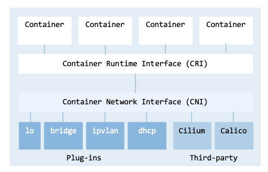
CNI architecture.#
Kubernetes uses low-level plugins to handle networking on the node’s network. For example, the bridge plugin sets up a virtual bridge on a node to connect Pods, and the DHCP plugin dynamically provides IP addresses via a DHCP server. While Kubernetes provides basic networking functionality, third-party CNI plugins, such as Cilium and Calico, offer additional features such as network policies, security, and efficient routing.
Setting up a Pod’s network involves the control plane, the kubelet, and the CNI provider. The process can be broken down into five primary phases:
Phase 1: Scheduling (Control Plane)
Pod Creation in API Server: A Pod object is created in the Kubernetes API server. The request is persisted in etcd.
Scheduling Decision: The kube-scheduler selects an appropriate node based on resources, policies, and constraints.
Node Binding: The scheduler updates the Pod specification by setting
spec.nodeNameto the chosen node.
Phase 2: Kubelet Observation and Pod Setup
Pod Watch Event: The kubelet on the selected node observes the Pod assignment through its watch on the API server.
Pod Sandbox Request: The kubelet instructs the container runtime through the CRI to create a Pod sandbox.
Phase 3: Pod Sandbox and Networking Initialization
Pod Sandbox Creation (Pause Container): The container runtime creates the Pod sandbox, including a Linux network namespace and a pause container.
CNI Plugin Invocation: The runtime invokes the CNI plugin with the ADD command to configure networking for the Pod.
IP Address Allocation (IPAM): The CNI plugin allocates a unique IP address for the Pod from the configured IPAM range.
Virtual Ethernet Pair Setup: The CNI plugin creates a veth pair, placing one end inside the Pod namespace and the other on the host.
In-Pod Network Configuration: The CNI plugin configures routes, default gateway, and DNS settings inside the Pod network namespace.
Phase 4: Host and Cluster Networking Integration
Host Network Rules and Cluster Routing: The CNI configures host-level NAT/masquerading rules and, depending on the implementation, may advertise routes (e.g., BGP), configure overlays (VXLAN/Geneve), or program eBPF data paths.
Phase 5: Container Start and Readiness
Container Startup and Pod Readiness: The container runtime starts the application containers. Once readiness probes succeed, the Pod transitions to the Running and Ready state.
sequence_diagram_pod_network illustrates the steps involved in setting up a Pod’s network.
Other steps, which we will not explore, include setting up DNS, service discovery,
and the application of network policies.
         sequenceDiagram
   autonumber

   participant API as kube-apiserver
   participant SCH as kube-scheduler
   participant KLT as kubelet
   participant CRI as Container Runtime (containerd/CRI-O)
   participant CNI as CNI Plugin

   %% 1-3: Scheduling (Control Plane)

   API->>SCH: Pod created in API server
   SCH->>API: Schedule Pod to node
   SCH->>API: Bind Pod (set spec.nodeName)

   %% 4-5: Kubelet observes + sandbox request

   KLT->>API: Watch Pod assigned to node
   KLT->>CRI: Create Pod sandbox (RunPodSandbox)

   %% 6-10: Sandbox + CNI networking

   CRI->>CRI: Create network namespace + pause container
   CRI->>CNI: Invoke CNI ADD (setup networking)

   CNI->>CNI: Allocate Pod IP (IPAM)
   CNI->>CNI: Create veth pair + attach host interface
   CNI->>CNI: Configure routes + DNS in Pod namespace

   CNI-->>CRI: Return network configuration

   %% 11-12: Start containers + readiness

   KLT->>CRI: Start containers in Pod sandbox
   KLT-->>API: Pod transitions to Running/Ready
The Pod networking lifecycle.#
This section provides a step-by-step guide to creating a simple CNI plugin in Bash.
files-bash-plugin shows the files of the plugin and how they relate
to the sequence diagram from sequence_diagram_pod_network.
Step ID |
Step Name |
File |
Description |
|---|---|---|---|
CNI plugin |
|||
Create bridge |
|||
CNI configuration |
|||
6 |
Create Pod |
||
8 |
Allocate IP |
||
9 |
Configure interface |
||
10 |
Configure iptables |
||
10 |
Configure routes and connectivity |
This section relies on utility scripts to help deploy the plugin
(util-deploy-plugin.sh)
and to monitor the network
(util-show-network.sh)
of the CNI plugin.
Specification#
The CNI specification defines three important elements:
Network configuration
Execution protocol
Result types
The network configuration contains information to be used by the container runtime and plugins. It is a JSON object with information about cniVersion, name, and type. Additional fields specific to a plugin can also be defined, e.g., bridge_name to use when setting up the networking. Plugins receive configuration via stdin.
The execution protocol defines the interaction between the CNI and the
plugin binary.
When the container runtime calls the CNI plugin, it passes several standard
environment variables to it.
These variables provide context information that the plugin needs to configure
the network.
cni-plugin-env lists the environment variables passed to a CNI plugin.
The result types are the output of the plugin after executing a command.
The Container Runtime (containerd/CRI-O) receives the result and passes the
necessary details back to the orchestrator.
For example, it reads the interfaces and ips from a success result
to ensure the rest of the cluster knows how to reach that specific Pod.
Variable |
Description |
Example |
|---|---|---|
CNI_COMMAND |
Command executed (e.g., ADD, DEL, CHECK). |
ADD |
CNI_ CONTAINERID |
ID of the container. |
f1d2d2f9d2f0 |
CNI_NETNS |
Path to the network namespace. |
/proc/123/ns/net |
CNI_IFNAME |
Name of the interface. |
eth0 |
CNI_ARGS |
Optional arguments |
“FOO=BAR;ABC=123” |
CNI_PATH |
Search path for plugins. |
/opt/cni/bin |
There are also standard Kubernetes environment variables injected into Pods (e.g., KUBERNETES_SERVICE_HOST and KUBERNETES_SERVICE_PORT).
When calling the plugin, the container runtime (the caller) sets the
CNI_COMMAND environment variable with the operation being invoked,
as shown in cni-plugin-bash.
The execution protocol defines four main operations: ADD, DEL, CHECK, and VERSION.
ADD: Create the network interface for the Pod.
DEL: Remove the network interface when a Pod is deleted.
CHECK: Verify the health of the network configuration.
VERSION: Returns the version of the protocol in use.
The code shown in cni-plugin-bash is the complete implementation.
#!/bin/bash -e
# The -e in the shebang does the same thing as set -e (Exit on Error).

exec 3>&1
mkdir -p /var/log/cni
exec &>> /var/log/cni/cni-plugin-bash.log

echo "$(date): Executing cni-plugin-bash"

source /opt/cni/bin/cni-plugin-if.sh
source /opt/cni/bin/cni-plugin-ip.sh
source /opt/cni/bin/cni-plugin-bridge.sh
source /opt/cni/bin/cni-plugin-iptables.sh
source /opt/cni/bin/cni-plugin-connectivity.sh

KUBECONFIG_FILE="/home/ubuntu/.kube/config"
NODE_NAME=$(hostname)
CNI_CONFIG=$(cat /dev/stdin)
CNI_SUBNET=$(kubectl --kubeconfig "$KUBECONFIG_FILE" get node "$NODE_NAME" -o jsonpath='{.spec.podCIDR}')
CNI_SUBNET_SZ=$(echo "$CNI_SUBNET" | awk -F  "/" '{print $2}')
CNI_BRIDGE_NAME=$(echo "$CNI_CONFIG" | jq -r ".bridge")
CNI_DEBUG=$(echo "$CNI_CONFIG" | jq -r ".debug")

echo "NODE_NAME: ${NODE_NAME}"
echo "CNI_COMMAND: ${CNI_COMMAND}"
echo "CNI_CONTAINERID: ${CNI_CONTAINERID}"
echo "CNI_NETNS: ${CNI_NETNS}"
echo "CNI_IFNAME: ${CNI_IFNAME}"
echo "CNI_ARGS: ${CNI_ARGS}"
echo "CNI_CONFIG: ${CNI_CONFIG}"
echo "CNI_SUBNET: ${CNI_SUBNET}"
echo "CNI_SUBNET_SZ: ${CNI_SUBNET_SZ}"
echo "CNI_BRIDGE_NAME: ${CNI_BRIDGE_NAME}"

GATEWAY=""
IP_ADDR=""

if [[ ${CNI_DEBUG} -gt 0 ]]; then set -x; fi

case ${CNI_COMMAND} in
    ADD)
        create_bridge ${CNI_BRIDGE_NAME}
        allocate_ip ${CNI_SUBNET}
        config_interface ${CNI_BRIDGE_NAME} ${CNI_NETNS} \
                         ${CNI_CONTAINERID} ${CNI_IFNAME} \
                         ${CNI_SUBNET_SZ} ${GATEWAY} ${IP_ADDR}
        config_iptables ${CNI_SUBNET}
        config_connectivity
        ;;
    DEL)
        CONTAINER_IP=$(echo "$CNI_CONFIG" | jq -r ".prevResult.ips[0].address" | sed 's:/24::')
        if [ "$VALUE" != "null" ]; then
            deallocate_ip $CONTAINER_IP
        else
            echo "IP is null. Not returning IP."
        fi
        echo "Deleting network for container $CNI_CONTAINERID"
        echo "Namespace $CNI_NETNS (IP: $CONTAINER_IP)"
        rm -rf /var/run/netns/$CNI_CONTAINERID
        ;;
    CHECK)
        # Implement check logic if needed
        ;;
    VERSION)
        echo '{
          "cniVersion": "0.4.0",
          "supportedVersions": [ "0.4.0", "0.4.1" ]
        }' >&3
        ;;
    *)
        echo "Unknown CNI_COMMAND: ${CNI_COMMAND}" >&2
        exit 1
        ;;
esac
When networking is successfully configured for a Pod, the plugin must output a JSON object with information about interfaces, MAC and IP addresses, namespaces, gateways, etc.
The script starts by redirecting all output to a log file for debugging, while preserving the original stdout file descriptor for later restoration. It saves stdout to file descriptor 3 and redirects both stdout and stderr to /var/log/cni/cni-plugin-bash.log, appending to the file if it already exists.
exec 3>&1
mkdir -p /var/log/cni
exec &>> /var/log/cni/cni-plugin-bash.log
The following section initializes several variables with information coming from the configuration file. The bridge name and debug level are stored in this file.
KUBECONFIG_FILE="/home/ubuntu/.kube/config"
NODE_NAME=$(hostname)
...
CNI_BRIDGE_NAME=$(echo "$CNI_CONFIG" | jq -r ".bridge")
CNI_DEBUG=$(echo "$CNI_CONFIG" | jq -r ".debug")
Afterwards, the script prints the content of the environment variables passed to the plugin. These variables provide context for the network configuration.
echo "NODE_NAME: ${NODE_NAME}"
echo "CNI_COMMAND: ${CNI_COMMAND}"
...
echo "CNI_SUBNET_SZ: ${CNI_SUBNET_SZ}"
echo "CNI_BRIDGE_NAME: ${CNI_BRIDGE_NAME}"
The last part of the script provides the implementation to respond to the ADD, DEL, CHECK, and VERSION commands. The ADD command executes the following functions:
allocate_ip ${CNI_SUBNET}
create_bridge ${CNI_BRIDGE_NAME}
config_interface ${CNI_BRIDGE_NAME} ${CNI_NETNS} \
                 ${CNI_CONTAINERID} ${CNI_IFNAME} \
                 ${CNI_SUBNET_SZ} ${GATEWAY} ${IP_ADDR}
config_iptables ${CNI_SUBNET}
config_routing
Since the most important command is the ADD, the following sections describe: bridge creation, IP allocation, interface configuration, iptables configuration, and routing configuration.
Configuration#
The CNI configuration file is typically formatted using the JSON format.
For our plugin, we created the configuration file named 10-cni-plugin-bash.conf
shown in cni-plugin-bash-conf.
There are several mandatory keys that are required for a valid CNI configuration,
namely, cniVersion, name, and type.
The numerical prefix 10 determines the order in which the CNI plugins are
executed when multiple CNI configurations are present.
The numerical prefix (i.e., 10) is a convention used to ensure the primary
network config needed is the one sorted first (e.g., 10-bridge.conf will be
picked over 20-flannel.conf).
{
    "cniVersion": "0.4.0",
    "name": "cni-bash-net",
    "type": "cni-plugin-bash.sh",
    "bridge": "cni0",
    "debug": 1
}
The field type must match the filename of the executable in the CNI binary directory (usually /opt/cni/bin). The configuration specifies one additional field which is not part of the specification: the name to give to the bridge that will be created.
Create bridge#
CNI plugins commonly use network bridges to enable communication across multiple network interfaces. A network bridge is a virtual network device that operates at Layer 2 (Data Link layer). Each Pod has a network interface that is connected to the bridge, enabling communication between Pods.
To prevent IP conflicts across the cluster, the kube-controller-manager assigns a unique, dedicated subnet called a podCIDR (Classless Inter-Domain Routing) to each node from the overall Cluster CIDR. This assignment happens when a node first registers with the cluster. The CNI plugin then uses this assigned range to configure the local bridge and assign individual IPs to Pods.
You can verify which subnets have been assigned to your nodes using the following command:
kubectl get nodes -o json | \
    jq -r '.items[] | .metadata.name + ": " + (.spec.podCIDR // "No podCIDR")'

control-plane: 10.244.0.0/24
worker0: 10.244.1.0/24
worker1: 10.244.2.0/24
The deployment has three nodes assigned with subnets 10.244.0.0/24 (control-plane), 10.244.1.0/24 (worker0), and 10.244.2.0/24 (worker1).
As shown in cni-create-bridge, the script to create the bridge uses
the same command to identify the subnet to use.
Typically, the bridge itself is assigned the first valid IP in the podCIDR
(e.g., 10.244.1.1), which then serves as the default gateway for all Pods
on that node.
#!/bin/bash

KUBECONFIG_FILE="/home/ubuntu/.kube/config"

create_bridge() {
    local BRIDGE_NAME="$1"
    local NODE_NAME
    local PODCIDR

    if ip link show "$BRIDGE_NAME" > /dev/null 2>&1; then
        echo "Bridge $BRIDGE_NAME already exists. Skipping."
        return 0
    fi

    NODE_NAME=$(hostname)
    PODCIDR=$(kubectl --kubeconfig "$KUBECONFIG_FILE" get node "$NODE_NAME" -o jsonpath='{.spec.podCIDR}')

    if [ $? -ne 0 ]; then
        echo "Failed to get PodCIDR for node $NODE_NAME."
        exit 1
    fi

    if [ -z "$PODCIDR" ]; then
        echo "PodCIDR is not set for node $NODE_NAME."
        exit 1
    fi

    echo "PodCIDR for node $NODE_NAME is $PODCIDR"

    PODCIDR_GW=$(echo $PODCIDR | sed "s:0/24:1:g")

    sudo ip link add name "$BRIDGE_NAME" type bridge
    sudo ip link set "$BRIDGE_NAME" up
    sudo ip addr add "$PODCIDR_GW/24" dev "$BRIDGE_NAME"

    echo "Bridge $BRIDGE_NAME created."

    return 0
}
To simplify the deployment workflow, the plugin ensures the bridge is “up”
before any Pod is added.
If the bridge does not exist during the ADD command execution, the script
initializes it immediately.
While this section focuses on the standard Linux Bridge (see Section Linux Bridge), more advanced environments may use an Open vSwitch bridge for enhanced traffic management, as described in Section Open vSwitch.
Allocate IP#
Next, the plugin is responsible for allocating an IP address from the bridge to assign to the Pod. The method for obtaining an IP address depends on the CNI plugin and its configuration. It is common for CNI plugins to interact with an IP Address Management (IPAM) plugin to manage the allocation and deallocation of IP addresses. More sophisticated plugins have their own IPAM functionality. Others will rely on external IPAM systems such as DHCP servers. The CNI plugin can find the IPAM configuration from its configuration file.
For our Bash CNI plugin, we use a custom, built-in IPAM functionality
(cni-plugin-ip.sh).
While rudimentary, it is simple and illustrates the (de)allocation of IP addresses.
The script provides functionality for managing a pool of IP addresses,
including initializing an IP pool file, allocating IP addresses, validating
IP addresses, and returning IP addresses to the pool.
The script to allocate an IP has four main functions:
initialize_pool: It initializes the IP address pool file with a range of IP addresses for a given subnet. It generates IP addresses from x.x.x.2 to x.x.x.254 and writes them to the pool file /tmp/ip_pool.txt.
select_ip: Selects the first IP address from the pool and removes it from the pool file.
allocate_ip: Returns the selected IP and sets the gateway IP address by replacing the last octet of the IP with 1.
deallocate_ip: Returns an IP address to the pool if it is valid and not already in the pool file.
In case IPs are allocated but not properly deallocated, the pool file must be manually deleted from the file system to reset the state. Be aware that in a Linux environment, /tmp is typically cleared on system reboot. Furthermore, automated utilities (such as systemd-tmpfiles) may periodically clean /tmp, which would inadvertently delete the IPAM state file while Pods are still actively running. For persistent local data, using a directory like /var/lib/cni/ is the standard convention.
In a real-world scenario, if two Pods are created at the exact same millisecond,
two processes might try to read/write /tmp/ip_pool.txt simultaneously.
To mitigate this, you can modify the script to use file locking (flock) to
ensure mutual exclusion and prevent assigning the same IP to two different Pods.
Configure interface#
The CNI specification requires the caller (typically kubelet via container runtime) to create a network namespace for the Pod and provide it via CNI_NETNS environment variable. The caller provides a path to the container’s network namespace file via the environment variable. However, because this path varies depending on the container runtime, it is often not directly visible to the ip netns tool. The CNI_IFNAME environment variable specifies the name of the network interface for the container (typically eth0). It is also provided by the caller.
The script cni-plugin-if.sh
(cni-plugin-if) sets up networking for containers by configuring the
network interface.
The Bash script creates the symbolic link /var/run/netns/<container_id> to
the container’s network namespace to make it accessible through a well-known path.
#!/bin/bash -e

function generate_veth_name() {
    local BASE_NAME=$1
    local rand=$(tr -dc 'a-f0-9' < /dev/urandom | head -c4)
    local VETH_NAME="veth${rand}-${BASE_NAME}"
    echo $VETH_NAME
}

function link_ns_to_container_id() {
    local NETNS=$1
    local CONTAINER_ID=$2
    mkdir -p /var/run/netns/
    ln -sfT ${NETNS} /var/run/netns/${CONTAINER_ID}
    echo "ln -sfT ${NETNS} /var/run/netns/${CONTAINER_ID}"
}

function create_veth_pair() {
    local BRIDGE_NAME=$1
    local CONTAINER_ID=$2
    local IFNAME=$3

    HOST_VETH=$(generate_veth_name ${BRIDGE_NAME})
    echo "link add ${IFNAME} type veth peer name ${HOST_VETH}"
    ip link add ${IFNAME} type veth peer name ${HOST_VETH}
    echo "connect interface ${IFNAME} to namespace ${CONTAINER_ID}"
    ip link set ${IFNAME} netns ${CONTAINER_ID}
    echo "connect interface ${HOST_VETH} to bridge ${BRIDGE_NAME}"
    ip link set ${HOST_VETH} master ${BRIDGE_NAME}
    ip link set ${HOST_VETH} up
}

function config_ns() {
    local CONTAINER_ID=$1
    local IFNAME=$2
    local SUBNET_SZ=$3
    local GATEWAY=$4
    local IP_ADDR=$5

    ip netns exec ${CONTAINER_ID} ip link set ${IFNAME} up
    ip netns exec ${CONTAINER_ID} ip addr add ${IP_ADDR}/${SUBNET_SZ} dev ${IFNAME}
    ip netns exec ${CONTAINER_ID} ip route add default via ${GATEWAY} dev ${IFNAME}

    MAC_ADDR=$(ip netns exec ${CONTAINER_ID} ip link show ${IFNAME} | awk '/ether/ {print $2}')

    echo "$MAC_ADDR"
}

function config_interface {
    local BRIDGE_NAME=$1
    local NETNS=$2
    local CONTAINER_ID=$3
    local IFNAME=$4
    local SUBNET_SZ=$5
    local GATEWAY=$6
    local IP_ADDR=$7
    local MAC_ADDR

    link_ns_to_container_id "$NETNS" "$CONTAINER_ID"
    create_veth_pair "$BRIDGE_NAME" "$CONTAINER_ID" "$IFNAME"
    MAC_ADDR=$(config_ns "$CONTAINER_ID" "$IFNAME" "$SUBNET_SZ" "$GATEWAY" "$IP_ADDR")

    cat <<EOF >&3
{
    "cniVersion": "0.4.0",
    "interfaces": [
        {
            "name": "${IFNAME}",
            "mac": "${MAC_ADDR}",
            "sandbox": "${NETNS}"
        }
    ],
    "ips": [
        {
            "version": "4",
            "address": "${IP_ADDR}/${SUBNET_SZ}",
            "gateway": "${GATEWAY}",
            "interface": 0
        }
    ]
}
EOF
}
The script’s primary functions include:
generate_veth_name: Generates a unique name and consistent naming convention for a veth interface connecting the Pod to the bridge. The random 4-character string helps ensure that the host-side veth name is unique, while the prefix (such as veth) clearly identifies the interface type in the host network namespace.
link_ns_to_container_id: Maps the runtime-provided namespace path to a well-known path (/var/run/netns/<container_id>), allowing the use of
ip netns execfor subsequent configuration steps.create_veth_pair: Creates a veth pair in the host namespace, moves one end into the container’s network namespace, and attaches the remaining host-side end to the bridge.
config_ns: Configures the network settings of the container’s network namespace, including setting the IP address, subnet mask, and default gateway. The function returns the MAC address of the network interface.
config_interface: The entry point that orchestrates the functions above. It ensures all resources are created in the correct order and formats the final JSON output required by the CNI specification.
The execution concludes by outputting a JSON object to stdout,
providing the container runtime with the interface details,
IP addresses, and routing rules necessary for Pod connectivity.
Configure NAT#
All containers in a Pod share a single network namespace and IP address. Thus, they can communicate with each other using the localhost or the Pod’s IP address. However, enabling communication between different Pods – or between a Pod and the outside world – requires the CNI plugin to configure host-level routing, packet filtering, and Network Address Translation (NAT).
By default, the Linux kernel is not configured to act as a router. To route packets between the container’s network namespace and the external network, IP forwarding must be enabled.
$ sudo sysctl -w net.ipv4.ip_forward=1
Pods attached to the same bridge on the same node occupy the same Layer 2 segment.
They can communicate directly as long as they belong to the same IP subnet and
host-level firewall rules do not interfere.
The Linux kernel uses the iptables FORWARD chain to manage this traffic.
To ensure traffic isn’t blocked in this development environment, the default
policy can be set to ACCEPT:
$ sudo iptables -P FORWARD ACCEPT
Note: In production environments, a default DROP policy is standard practice, paired with precise explicit rules targeting only valid Pod-to-Pod and egress traffic paths.
Pods can often ping their local host even if the host and the namespace are on different subnets. The node needs to be configured to route packets between the subnets, and IP forwarding must be enabled. Since the veth pair connects the namespace to the bridge, and the bridge is connected to the host, there is a link between the namespace and the node’s network stack. However, this is not sufficient. The Pod needs to route the default traffic to the bridge’s gateway, and the node needs to route the traffic to the namespace via the bridge. The routing from the Pod to the node was previously configured by the interface configuration script via the default gateway assignment. The routing from the node to the bridge is set up automatically when the bridge is created.
The script cni-plugin-iptables.sh
sets up the iptables in case they are not properly configured, as shown
in cni-plugin-iptables:
#!/bin/bash

# usage example
# config_iptables "10.244.1.0/24"

function config_iptables() {
    local SUBNET="$1"
    local COMMENT="cni-plugin-bash traffic"

    echo "Enabling IP forwarding."
    sudo sysctl -w net.ipv4.ip_forward=1

    echo "Setting up iptables rules."
    if sudo iptables -t filter -S FORWARD | grep -q -F "$COMMENT"; then
        echo "Rule already exists in FORWARD chain."
    else
        echo "Setting FORWARD chain."
        sudo iptables -t filter -A FORWARD -s "$SUBNET" -m comment --comment "$COMMENT" -j ACCEPT
        sudo iptables -t filter -A FORWARD -d "$SUBNET" -m comment --comment "$COMMENT" -j ACCEPT
    fi

    echo "Setting up masquerading."
    if sudo iptables -t nat -S POSTROUTING | grep -q -F "$COMMENT"; then
        echo "Rule already exists in POSTROUTING chain."
    else
        sudo iptables -t nat -A POSTROUTING -s "$SUBNET" -m comment --comment "$COMMENT" -j MASQUERADE
    fi

    echo "Configuration iptables completed."
}
Pods typically use private IP addresses (from the podCIDR) that are not routable outside the cluster. When a Pod initiates a connection to an external system (like 8.8.8.8), the node must perform Source NAT (SNAT). By using the MASQUERADE target in the POSTROUTING chain, the host replaces the Pod’s source IP with its own public/LAN IP.
$ sudo iptables -t nat -A POSTROUTING -s "$SUBNET" -m comment --comment "$COMMENT" -j MASQUERADE
It is now possible to ping an external IP on the internet from within the Pod:
$ kubectl exec -it <pod-name> -- ping 8.8.8.8

PING 8.8.8.8 (8.8.8.8) 56(84) bytes of data.
64 bytes from 8.8.8.8: icmp_seq=1 ttl=116 time=8.88 ms
64 bytes from 8.8.8.8: icmp_seq=2 ttl=116 time=9.14 ms
^C
--- 8.8.8.8 ping statistics ---
2 packets transmitted, 2 received, 0% packet loss, time 1002ms
rtt min/avg/max/mdev = 8.884/9.012/9.141/0.128 ms
To persist the iptables rules after a reboot, install an administration utility such as iptables-persistent and store the active rules to a file:
$ iptables-save > /etc/iptables/rules.v4
Configure connectivity#
To enable communication between Pods in different nodes, traffic must be directed using L3 routing. In this underlay configuration, each node acts as a router for its assigned podCIDR.
The node must be configured to forward packets to and from the subnet where Pods are assigned. In multi-node clusters, static routes are needed to direct inter-node traffic between nodes. The Pod network CIDR assigned to a node (e.g., 10.244.1.0/24) represents the IP address range assigned to Pods in a node (e.g., worker0). The cluster-wide Pod network CIDR (e.g., 10.244.0.0/16) represents the IP address range assigned to all Pods. To enable communication within a node and across nodes, we can apply the following rules: In the case two Pods in different hosts need to communicate (e.g., from Pod pod1 to Pod pod3), we must provision the host of Pod pod1 with a routing table entry specifying the next-hop gateway for that destination subnet. When a request is sent from container 10.244.1.4 to container 10.244.2.3, worker0 receives the packet via the local bridge but lacks a routing table entry specifying how to reach the remote 10.244.2.0/24 subnet.
The script cni-plugin-connectivity.sh
(shown in cni-plugin-connectivity)
automates the discovery and configuration of these static routes.
The script discovers the cluster topology, loops through the remote nodes,
and applies the required paths using the ip route add command.”
#!/bin/bash

KUBECONFIG_FILE="/home/ubuntu/.kube/config"


function check_kubectl() {
    if ! command -v kubectl &> /dev/null; then
        echo "kubectl could not be found."
        exit 1
    fi
}

function get_nodes_and_cidrs() {
    kubectl --kubeconfig "$KUBECONFIG_FILE" get nodes \
            -o jsonpath='{range .items[*]}{.metadata.name} {.spec.podCIDR}{"\n"}{end}'
}

function get_node_ip() {
    local node=$1
    kubectl --kubeconfig "$KUBECONFIG_FILE" get node "$node" \
            -o jsonpath='{.status.addresses[?(@.type=="InternalIP")].address}'
}

function add_route() {
    local cidr=$1
    local node_ip=$2

    if ip route show | grep -q "$cidr"; then
      echo "Route for $cidr already exists. Skipping."
    else
      echo "Adding route for CIDR $cidr via node $node_ip"
      sudo ip route add "$cidr" via "$node_ip"
    fi
}

function config_connectivity() {

    echo "Configuring connectivity between nodes."

    check_kubectl
    nodes=$(get_nodes_and_cidrs)
    echo "$nodes" | while read -r node cidr; do
        if [[ -z "$cidr" ]]; then
            echo "No CIDR found for node $node. Skipping."
            continue
        fi

        node_ip=$(get_node_ip "$node")

        if [[ -z "$node_ip" ]]; then
            echo "No IP address found for node $node. Skipping."
            continue
        fi

        add_route $cidr $node_ip

    done

    echo "Configuration connectivity completed."
}
get_nodes_and_cidrs(): Retrieves the list of nodes in a Kubernetes cluster along with their associated podCIDRs using the kubectl command-line tool.
get_node_ip(): Retrieves the internal IP address of a specific node in a Kubernetes cluster using the kubectl command-line tool.
add_route(): Adds a route on the local node to reach a remote node’s Pod CIDR via the remote node’s IP address. This enables Pod-to-Pod communication across nodes.
config_routing(): Configures the routing rules on the local node to all other nodes and their podCIDR information in a Kubernetes cluster.
For a cluster with \(N\) nodes, the script establishes \(N - 1\) routes on each node, resulting in a cluster-wide total of \(N * (N - 1)\) static routes. While efficient for small topologies, this \(O(N^2)\) complexity becomes difficult to manage at scale.
In case the Kubernetes cluster has nodes in different LANs, possibly distributed geographically across data centers, it is required to set up, for example, a VXLAN tunneling (overlay), as described in the section on VXLAN.
Hands-on implementation#
Install Kubernetes#
Before deploying the CNI plugin, ensure you have a running Kubernetes cluster. You can follow the instructions in the Cluster Deployment chapter to set up a Kubernetes cluster using Multipass and kubeadm. Your cluster should have at least two worker nodes to test inter-node Pod-to-Pod communication.
$ cluster_manager.sh -n 3 -c 2 -m 2G -t cilium
The options are described below:
-n: Total number of nodes (1 control-plane node and n-1 worker nodes)
-c: CPU cores per node
-m: Memory per node
-t: Network type (e.g., cilium, calico)
Check the health and status of the nodes in the Kubernetes cluster.
$ kubectl get nodes

NAME            STATUS   ROLES           AGE   VERSION
control-plane   Ready    control-plane   86s   v1.35.0
worker0         Ready    worker          72s   v1.35.0
worker1         Ready    worker          69s   v1.35.0
Uninstall CNI#
If you already have a CNI plugin running (e.g., Cilium), you need to uninstall it. Start by draining the nodes to ensure that no workloads are running during the transition, reducing the risk of disruption.
$ kubectl drain <node-name> --ignore-daemonsets --delete-emptydir-data
Since CNI plugins are usually deployed as a set of Pods in the kube-system namespace, you can list the Pods in this namespace to identify the CNI plugin.
$ kubectl get pods -n kube-system

NAME                 READY   STATUS    RESTARTS        AGE
cilium-br6q9         1/1     Running   0               2d21h
cilium-cbfml         1/1     Running   0               2d21h
cilium-envoy-2w8tb   1/1     Running   0               2d21h
... 14 Pods not shown ...
If you are using Cilium, remove it using the following command:
$ helm uninstall cilium -n kube-system

release "cilium" uninstalled
Also, remove the CNI configuration files (usually located in /etc/cni/net.d/) on all nodes (control-plane, worker0, and worker1). For example, on worker0:
$ multipass exec worker0 -- sudo ls /etc/cni/net.d/
05-cilium.conflist
Then, delete the Cilium configuration file:
$ multipass exec worker0 -- sudo rm /etc/cni/net.d/05-cilium.conflist
Install Bash plugin#
To install the Bash plugin, we need to transfer the plugin scripts and configuration file to each Kubernetes node. The directory /opt/cni/bin/ stores all available CNI plugins. The CNI manager (such as kubelet or another orchestrator) uses this folder to discover CNI plugins. For example, on worker0:
$ ubuntu@worker0:/opt/cni/bin$ ll

total 319648
drwxr-xr-x 2 root root     4096 Jul 19 11:56 ./
drwxr-xr-x 3 root root     4096 Jul 15 14:57 ../
...
-rwsr-xr-x 1 root root 62005022 Jul 15 14:58 bridge
-rwxr-xr-x 1 root root  2342446 Jul 15 14:58 cilium-cni
...
Back on the main host, make all the Bash scripts executable and run the
deployment script
util-deploy-plugin.sh
to copy all the CNI scripts and configuration files to the respective directories:
$ cd ~/Work/git/kubernetes/chapters/cluster_networking/scripts/cni-plugin-bash
$ chmod +x *.sh
$ util-deploy-plugin.sh
The script uses Multipass to transfer the files.
#!/bin/bash

USER_DIR=/home/ubuntu/cni-plugin-bash/
SYSTEM_DIR=/opt/cni/bin/
LOG_FILE=/var/log/cni/cni-plugin-bash.log

# Define the files and directories to be transferred
# Format: "source_file initial_directory final_directory"
FILES=(
  "10-cni-plugin-bash.conf ${USER_DIR} /etc/cni/net.d/"
  "cni-plugin-bash.sh ${USER_DIR} ${SYSTEM_DIR}"
  "cni-plugin-bridge.sh ${USER_DIR} ${SYSTEM_DIR}"
  "cni-plugin-ip.sh ${USER_DIR} ${SYSTEM_DIR}"
  "cni-plugin-if.sh ${USER_DIR} ${SYSTEM_DIR}"
  "cni-plugin-iptables.sh ${USER_DIR} ${SYSTEM_DIR}"
  "cni-plugin-connectivity.sh ${USER_DIR} ${SYSTEM_DIR}"
  "util-apply-pod.sh ${USER_DIR} ${SYSTEM_DIR}"
  "util-deploy-plugin.sh ${USER_DIR} ${SYSTEM_DIR}"
  "util-show-network.sh ${USER_DIR} ${SYSTEM_DIR}"
)

echo "Discovering Kubernetes nodes..."
NODE_NAMES=$(kubectl get nodes -o jsonpath='{.items[*].metadata.name}')

if [ -z "$NODE_NAMES" ]; then
  echo "No nodes found. Exiting."
  exit 1
fi

NODE_ARRAY=($NODE_NAMES)

for NODE in "${NODE_ARRAY[@]}"; do
  echo "Processing ${NODE}..."

  echo "Deleting log file ${LOG_FILE}"
  multipass exec "$NODE" -- sudo rm -rf "${LOG_FILE}"

  for FILE_ENTRY in "${FILES[@]}"; do
    IFS=' ' read -r SOURCE_FILE INITIAL_DIR FINAL_DIR <<< "$FILE_ENTRY"

    echo "Creating directory ${INITIAL_DIR} on ${NODE}"
    multipass exec "$NODE" -- sudo mkdir -p "$INITIAL_DIR"
    multipass exec "$NODE" -- sudo chown ubuntu:ubuntu "$INITIAL_DIR"

    echo "Transferring ${SOURCE_FILE} to ${NODE}:${INITIAL_DIR}"
    multipass transfer "$SOURCE_FILE" "${NODE}:${INITIAL_DIR}"

    echo "Copying ${SOURCE_FILE} from ${INITIAL_DIR} to ${FINAL_DIR} on ${NODE}"
    multipass exec "$NODE" -- sudo cp "${INITIAL_DIR}/${SOURCE_FILE}" "${FINAL_DIR}/${SOURCE_FILE}"
  done

  echo "File processing complete on ${NODE}."
done

echo "File transfer and processing complete for all nodes."
Display networks#
To display the networking configuration of the CNI Bash plugin, create the
deployment shown in cluster_networking_arch which contains four Pods:
pod1 and pod2 on worker0 and Pods pod3 and pod4 on worker1.
The architecture diagram highlights five critical areas: bridge, IP, interface,
NAT, and routing.
The Kubernetes cluster supporting the testbed consists of one control-plane node and two worker nodes, all running Ubuntu 24.04 LTS with the same Kubernetes version (v1.35.0) and container runtime (containerd 1.7.19). The control plane node (control-plane) is responsible for managing the cluster, while the worker nodes (worker0 and worker1) are responsible for running the application workloads.
$ kubectl get nodes -o wide

NAME            STATUS   ROLES           AGE   VERSION   INTERNAL-IP   ...
control-plane   Ready    control-plane   24m   v1.35.0   10.30.45.127
worker0         Ready    worker          23m   v1.35.0   10.30.45.39
worker1         Ready    worker          23m   v1.35.0   10.30.45.252
To prepare the testbed, use the file
util-apply-pod.sh
to deploy new Pods.
This script is useful for creating and managing a series of Pods with
sequentially numbered names (pod1, pod2, …).
For example:
$ util-apply-pod.sh worker0
$ util-apply-pod.sh worker0
$ util-apply-pod.sh worker1
$ util-apply-pod.sh worker1
The previous commands create four Pods: pod1 and pod2 on worker0, and pod3 and pod4 on worker1.
$ kubectl get pod -o wide

NAME   READY   STATUS    RESTARTS   AGE     IP           NODE      ...
pod1   1/1     Running   0          17m     10.244.1.5   worker0
pod2   1/1     Running   0          3m50s   10.244.1.6   worker0
pod3   1/1     Running   0          8s      10.244.2.5   worker1
pod4   1/1     Running   0          4s      10.244.2.6   worker1
Once networking is done, display the current bridge and routing configuration
of the worker nodes. The function in util-show-network
(util-show-network.sh)
shows the bridge link configuration, the IP addresses associated with the bridge,
the FORWARD chain in iptables, and the routing table.
#!/bin/bash

show_network_config() {
    local BRIDGE_NAME=$1
    local COMMENT="cni-plugin-bash traffic"

    echo "Printing bridge and routing configuration..."

    echo "Bridge links:"
    bridge link show

    echo "IP addresses for bridge $BRIDGE_NAME:"
    ip addr show "$BRIDGE_NAME"

    echo "iptables rules:"
    sudo iptables -t filter -S FORWARD | grep -F "$COMMENT"

    echo "Routing table:"
    ip route show
}

BRIDGE_NAME="cni0"
show_network_config "$BRIDGE_NAME"
On the worker nodes, the output should be similar to the following:
$ /opt/cni/bin/util-show-network.sh

Printing bridge and routing configuration...
Bridge links:
IP addresses for bridge cni0:
3: cni0: <NO-CARRIER,BROADCAST,MULTICAST,UP> mtu 1500 ...
    link/ether 02:03:8a:52:24:6b brd ff:ff:ff:ff:ff:ff
    inet 10.244.1.1/24 scope global cni0
    ...
iptables rules:
-A FORWARD -s 10.244.1.0/24 -m comment --comment "cni-plugin-bash traffic" -j ACCEPT
-A FORWARD -d 10.244.1.0/24 -m comment --comment "cni-plugin-bash traffic" -j ACCEPT
Routing table:
default via 10.236.217.1 dev ens3 proto dhcp src 10.236.217.141 metric 100
10.236.217.0/24 dev ens3 proto kernel scope link src 10.236.217.141 metric 100
10.236.217.1 dev ens3 proto dhcp scope link src 10.236.217.141 metric 100
10.244.0.0/24 via 10.236.217.248 dev ens3
10.244.1.0/24 dev cni0 proto kernel scope link src 10.244.1.1 linkdown
10.244.2.0/24 via 10.236.217.71 dev ens3
Verify connectivity#
Once the Pods are running, verification is conducted by executing the series of
tests listed in network_verification.
From |
Connecting to |
Target |
Results |
|
|---|---|---|---|---|
1 |
worker0 |
Bridge |
cni0 |
Successful |
2 |
worker0 |
Pod |
pod1 |
Successful |
3 |
pod1 |
Local host |
worker0 |
Successful |
4 |
pod1 |
Pod on the same host |
pod2 |
Successful |
5 |
pod1 |
Different node |
worker1 |
Successful |
6 |
pod1 |
Pod on a different host |
pod3 |
Successful |
7 |
pod1 |
External address |
8.8.8.8 |
Successful |
From inside a Pod, network connectivity can be verified using
kubectl exec -it <pod_name> -- ping <target>.
For example:
$ kubectl exec -it pod1 -- ping -c 3 8.8.8.8

PING 8.8.8.8 (8.8.8.8) 56(84) bytes of data.
64 bytes from 8.8.8.8: icmp_seq=1 ttl=118 time=9.08 ms
64 bytes from 8.8.8.8: icmp_seq=2 ttl=118 time=16.6 ms
64 bytes from 8.8.8.8: icmp_seq=3 ttl=118 time=8.44 ms

--- 8.8.8.8 ping statistics ---
3 packets transmitted, 3 received, 0% packet loss, time 2002ms
rtt min/avg/max/mdev = 8.435/11.362/16.576/3.696 ms
Troubleshooting#
Building a CNI plugin in Bash is an excellent way to understand the internals of Kubernetes networking. However, debugging Bash scripts called by the kubelet can be difficult because the environment is non-interactive and errors can be swallowed.
1. Logs and Events
If a Pod is stuck in ContainerCreating, the first step is to check the Kubernetes Event log. Check the ‘Events’ section at the bottom of the output. This often provides clearer error messages than the raw journal logs.
$ kubectl describe pod pod1
If the error is related to NetworkPlugin, follow the logs in real time on the worker nodes. Combine Kubelet logs and the custom plugin logs:
tail -f /var/log/cni/cni-plugin-bash.log &
sudo journalctl -u kubelet -f | grep cni
Once you identify the error, you can kill the tail process using the
command jobs followed by kill %1 (where %1 is the job number).
2. Mocking a CNI Call
You don’t need to wait for Kubernetes to trigger the CNI Bash script. You can manually mock a CNI ADD command to see if the logic breaks under specific scenarios.
export CNI_COMMAND=ADD
export CNI_CONTAINERID=test-cid-123
export CNI_NETNS=/var/run/netns/test-ns
export CNI_IFNAME=eth0
export CNI_PATH=/opt/cni/bin

cat /etc/cni/net.d/10-cni-plugin-bash.conf | sudo -E ./cni-plugin-bash.sh
3. Verify the Data Path
If the logs indicate “Success” but the Pod can’t ping anything, check the Linux networking stack.
Ensure that the bridge was actually created and has an IP address.
$ ip addr show cni0
$ ip link show type bridge
Verify that the veth pair is attached to the bridge
Check if the host knows how to route traffic to the Pod CIDR.
$ ip route | grep cni0
4. Inspecting the Namespace
Sometimes the script runs, but the configuration inside the container namespace is wrong (e.g., the default gateway is missing). Find the network namespace (netns) of the Pod and execute commands inside it using nsenter. nsenter enables you to enter another process’s namespaces from the host. Execute the commands ip route and ip addr inside the Pod’s network namespace to verify the configuration.
sudo nsenter -t $(sudo crictl inspect <container_id> | jq '.info.pid') \
    -n ip addr
sudo nsenter -t $(sudo crictl inspect <container_id> | jq '.info.pid') \
    -n ip route
5. Cleaning Up “Ghost” Rules
If you have conducted extensive testing and are still seeing issues, check for orphaned veth pairs and identify those without a peer interface:
$ ip link show | grep veth
You might need to flush the NAT table. Target the POSTROUTING chain specifically for the Pod subnet:
$ sudo iptables -t nat -S POSTROUTING
6. Restart Virtualization
If the underlying virtualization platform (Multipass) becomes unresponsive, restart the daemon to restore connectivity.
$ sudo snap restart multipass.multipassd